Overview of the Ray-Tracing Rendering Technique
Reading time: 27 mins.>One problem with discussing ray-tracing is that ray-tracing is an overloaded term.
Ray-tracing is a technique for computing the visibility between points. Light transport algorithms are designed to simulate the way light propagates through space (while interacting with objects). They are used (in short) to compute the color of a point in the scene. Do not mix ray tracing with light transport algorithms. They are two different things. Ray tracing is not a light-transport algorithm. It is only a technique to compute visibility between points.
Given a set of obstacles in Euclidean space, two points in the space are said to be visible to each other, ifthe line segment that joins them does not intersect any obstacles. (definition of [visibility](http://en.wikipedia.org/wiki/Visibility_(geometry)) on Wikipedia)
An Overview of the Ray-Tracing Rendering Technique
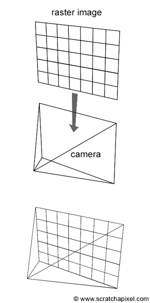
In the first lesson of this section, we have already quickly introduced you to the concept of rendering in general and how to produce images of 3D scenes using ray tracing in particular. We have mentioned the ray-tracing technique in other lessons such as the lesson Rendering an Image of a 3D Scene and Rasterization: a Practical Implementation but the goal in these lessons was more to highlight the differences between the rasterization and the ray-tracing techniques, which are the main two common frameworks (or rendering techniques) for rendering images of 3D objects.
Shall we re-introduce the ray-tracing rendering technique one more time? You should already be familiar with the concept but this lesson is the first in a series in which we will study techniques that are specific to ray-tracing so it seems like a good idea to review one more time what the method is about, how it works, the basic principles of the technique, and what the main differences between rasterization and ray-tracing are.
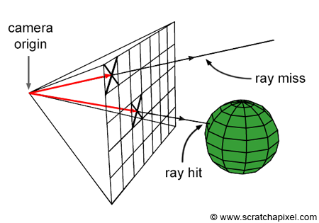
Ray-tracing is all about rays, and rays are one of the main topics of this lesson. We will learn what they are and how they can be defined in programming. As we know by now, a raster image is made out of pixels. One way of producing an image of a 3D scene is to somehow "slide" this raster image along the image plane of our virtual camera (Figure 1), and shoot rays through each pixel in the image, to find which part of the scene each pixel covers. The way we do that is simply by casting a ray originating from the eye (the camera position) and passing through the center of each pixel. We then find what object (or objects) from the scene, these rays intersect. If a pixel "sees" something surely it sees the object that is right in front of it in the direction pointed by that ray. The ray direction as we just mentioned can simply be constructed by tracing a line from the camera's origin to the pixel center and then extending that line into the scene (Figure 2).
Now that we know "what" a pixel sees, all we need to do is repeat this process for every pixel in the image. By setting up the pixel color with the color of the object that each ray passing through the center of each pixel intersects, then we can form an image of the scene as seen from a particular viewpoint. Note that this method requires looping over all the pixels in the image and casting a ray into the scene for each one of these pixels. The second step, the intersection step, requires looping over all the objects in the scene to test if a ray intersects any of these objects. Here is an implementation of this technique in pseudo-code:
// loop over all pixels
Vec3f *framebuffer = new Vec3f[imageWidth * imageHeight];
for (int j = 0; j < imageHeight; ++j) {
    for (int i = 0; i < imageWidth; ++i) {
        for (int k = 0; k < numObjectsInScene; ++k) {
            Ray ray = buildCameraRay(i, j);
            if (intersect(ray, objects[k]) {
                // do complex shading here but for now basic (just constant color)
                framebuffer[j * imageWidth + i] = objects[k].color;
            }
            else {
                // or don't do anything and leave it black
                framebuffer[j * imageWidth + i] = backgroundColor;
            }
        }
    }
}
Note that some of the rays might not intersect any geometry at all. For example, if you look at Figure 2, one of the rays does not intersect the sphere. In this particular case, we generally leave the pixel's color black or set it up to any other color we want the background to be (line 10).
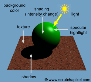
Note also that in the code above, we set the pixel color with the object color at the intersection point. Though objects from the real world don't look flat. They have complex appearances or looks (which is very hard to reproduce convincingly in painting for example - and that is because the appearance of objects is generally visually very complex). Their brightness changes depending on the amount of light they receive, some are shiny, some are matte, etc. The goal of photorealistic rendering is not only to depict accurately the geometry as seen from a given viewpoint (and solve the visibility problem) but also to simulate the appearance of objects convincingly. Thus, most likely this process involves something more complicated than just returning a constant color (which is what we have done in the code above). In computer graphics, the task of defining the object's actual color at any given point on its surface (knowing that this color changes depending as we just said on external parameters such as how much light an object receives as we all internal parameters such as how shiny or matter the object is) is called shading. It will take quite a few more lessons before we can start studying shading, but you must know about it at this stage.
Ray-tracing is said to be image-centric. The outer loops iterate over all the pixels in the image and the inner loop iterates over the objects in the scene. The rasterization algorithm in comparison is object-centric. It requires looping over all the geometric primitives in the scene (the outer loop), projecting these primitives onto the screen, and then looping over all pixels in the image to find which one of these pixels overlaps the screen projected geometry (the inner loop). The inner and outer loops in the two algorithms is swapped. Here is a quick implementation of the rasterization loops in pseudo-code (you can find a complete description of this algorithm in the lesson Rasterization: a Practical Implementation).
// loop over all pixels
Vec3f *framebuffer = new Vec3f[imageWidth * imageHeight];
for (int k = 0; k < numObjectsInScene; ++k) {
    // project object onto the scene using perspective projection
    ...
    for (int j = 0; j < imageHeight; ++j) {
        for (int i = 0; i < imageWidth; ++i) {
            if (pixelCoversGeometry(i, j, objects[k]) {
                framebuffer[j * imageWidth + i] = objects[k].color;
            }
        }
    }
}
As mentioned several times in the previous lessons, both rasterization and ray tracing can be used to solve the visibility problem. Though remember that the rendering process is a two steps process: it includes visibility and shading. Rasterization is good for visibility (and much faster than ray tracing) but not as good as ray tracing when it comes to shading. Ray tracing on the other hand can be used for both.
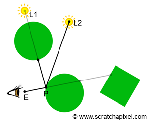
What is going to explain is pretty central to rendering, so take a moment to read it carefully. Often you will read that ray tracing is better than rasterization for shading but most textbooks fail to explain why. (Almost) everything in rendering is about computing the visibility between a point in space and the first visible surface in a given direction, or the visibility between two points. The former is used to solve the visibility problem, and the latter to solve things such as shadowing. Rasterization (combined with the depth-buffer algorithm) is very good to find the first visible surface but is inefficient to solve the visibility between two points. Ray-tracing on the other end can handle both cases efficiently. Finding the first visible surface is useful to solve the visibility problem. Thus both ray-tracing and rasterization do a good job of that. Shading, on the other hand, requires solving visibility between surfaces. This is used to compute shadows, soft shadows when area lights are used, and more generally global illumination effects such as reflection, refraction, indirect reflections, and indirect diffuse. For this particular part of the rendering process, ray tracing is thus more efficient than rasterization. But keep in mind that any technique that computes the visibility between points can be used for shading and solving the visibility problem. It doesn't have to either be ray-tracing or rasterization but ray-tracing is somehow the lazy way of doing it, though it comes at a price as we will see at the end of this chapter. We will come back to this important concept in the next chapter when we will talk about light transport algorithms.
Ray-tracing sounds like a much better method than rasterization when you look at it that way, though the main issue with ray-tracing is that it involves computing the intersection of rays with geometry which is a costly operation (i.e. slow). In real-time graphics applications, speed is more important than photo realism which is why GPUs use rasterization. When photo-realism is more important than speed, ray tracing is a much better choice, though it is harder to produce images with ray tracing at interactive frame rates and even less so at real-time frame rates.
Ray tracing isn't too slow; computers are too slow. (Kajiya 1986)
In summary, using ray tracing to compute photo-realistic images of 3D objects can be decomposed in essentially three steps:
-
Casting Rays: cast a ray for each pixel in the image
-
Ray-Geometry Intersection: test if a ray intersects any of the objects in the scene (this requires looping over all the objects for each cast ray).
-
Shading: find out what the object "looks like" at the intersection point between the ray and the object (if an intersection has occurred).
Let's now review these steps one by one.
Casting Rays into the scene
The first thing we need to do to create an image in ray tracing is to cast a ray for each pixel in the image. These rays are called camera or primary rays (because they are simply the first rays we will cast into the scene). As we will see later in this lesson, more rays can be spawned from primary rays. These other rays are called secondary rays. They are used to find if a given point in the scene is in shadow or to compute shading effects such as reflection or refraction. When a primary ray is cast into the scene, the next step is to find if it intersects any object in the scene.
When primary rays are used to solve the visibility problem, we can use the term ray-casting.
Generating primary or camera rays is the topic of the next lesson (Ray-Tracing: Generating Camera Rays).
Testing for Ray-Geometry Intersections
Testing if a ray intersects any object in the scene requires looping over all the objects in the scene and testing the current object against the ray.
Ray ray = buildCameraRay(i, j);
for (int k = 0; k < numObjects; ++k) {
    if (intersect(ray, objects[k]) {
        // this ray intersects objects[k]
    }
}
Geometry in 3D can be defined in many different ways. Simple shapes such as spheres, disks, and planes can be defined mathematically, or parametrically. The shapes of more complex objects can only be described using polygon meshes, subdivision surfaces or NURBS surfaces (or something equivalent).
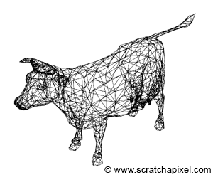
The first category of objects (objects represented mathematically) can often be tested for a ray intersection using a geometric or analytical approach. The ray-sphere intersection test for example can be resolved using both approaches. This is the topic of the lesson Ray-Tracing: Rendering Simple Shapes.
The main problem with the second category of objects is that ray-geometry intersection method needs to be implemented for each supported type of surface. NURBS surfaces for example can be ray-traced directly though the solution for doing so is very different from the solution being used to test the intersection between a ray and a polygon mesh. Thus, if you want to support all geometry types (subdivision surface, NURBS, polygon mesh), you need to write one ray-geometry intersection routine per supported type of geometry. This potentially adds a fair degree of complexity to the program's code. The alternative solution (which is the approach chosen by almost every professional program) is to convert each geometry type into the same internal representation, which is almost 99% of the cases, is going to be a triangulated polygon mesh. Ray-tracing loves triangles!
Why triangles? As suggested, first, it is a better approach to convert the different geometry types to the same internal geometry representation (a process also called tessellation), and it happens that converting almost any type of surface to a polygon mesh is generally easy. From there, converting a polygonal mesh to a triangulated mesh is also pretty straightforward (the only difficulty is with concave polygons). Though triangles are also advantageous because they can be used as a basic geometric primitive in both ray tracing and rasterization. Why both algorithms love triangles because they have interesting geometrical properties that other types don't have. They are co-planar which is not necessarily the case of faces with more than three vertices. Computing their barycentric coordinates using the edge function approach which we described in the lesson on rasterization is also straightforward. Barycentric coordinates play an important role in shading.
For this reason, a lot of research went into finding the best possible method for testing if a ray intersects a triangle. This problem can be solved geometrically but this is not necessarily the fastest method. Other methods using algebraic solutions have been developed over time. A good ray-triangle intersection routine is both fast and numerically stable. This topic will be studied in the lesson Ray-Tracing: Rendering a Triangle.
Polygonal meshes or other types of surfaces are thus converted to triangles. This can be done either before you load the geometry into the memory of your program (in your modeling tool, before you export the mesh to the renderer), or while you load the geometry at render time. We will use the second option in this series of lessons. Note though that now, not only each camera ray need to be tested against each object in the scene, but also against each triangle making up each polygon object in the scene. In other words, the loops now look like the following:
for (int j = 0; j < imageHeight; ++j) {
    for (int i = 0; i < imageWidth; ++i) {
        for (int k = 0; k < numObjects; ++k) {
            for (int n = 0; n < objects[k].numTriangles; ++n) {
                Ray ray = buildCameraRay(i, j);
                if (intersect(ray, objects[k].triangles[n])) {
                    framebuffer[j * imageWidth + i] = shade(ray, objects[k], n);
                }
            }
        }
    }
}
What this practically means, is that the time it takes to render a scene in ray tracing is directly proportional to the number of triangles the scene contains. This is not necessarily the case with rasterization. Of course the more triangles you have with a rasterizer the longer it takes to render the frame, though many of these triangles can be thrown away before the render even starts (for example the triangles facing away from the camera if back face culling is on). This is not possible in ray tracing for a reason we will explain in the shading part of this chapter. All triangles need to be stored in memory and each one of them needs to be tested when a ray is cast into the scene. The high-computational cost of ray tracing (and the fact that render time grows linearly with the number of triangles the scene contains) is one of the algorithm's main curses.
The Trace Function
In ray-tracing the inner loops (the loop over all the objects and all the triangles each object contains) are generally moved to a function which is typically called trace(). The function returns true if an object/triangle was intersected and false otherwise.
bool trace(
    const Vec3f& rayOrigin, const Vec3f &rayDirection,
    const Object* objects, const uint32_t &numObjects,
    uint32_t &objectIndex,
    uint32_t &triangleIndex
)
{
    bool intersect = false;
    for (uint32_t k = 0; k < numObjects; ++k) {
        for (uint32_t n = 0; n < objects[k].numTriangles; ++n)) {
            if (rayTriangleIntersect(rayOrigin, rayDirection, objects[k].triangles[n]) {
                intersect |= true;
                objectIndex = k;
                triangleIndex = n;
            }
        }
    }

    return intersect;
}

int main(...)
{
    ...
    uint32_t objectIndeix, triangleIndex;
    for (int j = 0; j < imageHeight; ++j) {
        for (int i = 0; i < imageWidth; ++i) {
            if (trace(rayOrigin, rayDirection,   objects, numObjects, objectIndex, triangleIndex)) {
                framebuffer[j * imageWidth + i] = shade(rayOrigin, rayDirection, objects[objectIndex], triangleIndex);
            }
        }
    }
    ...
   return 0;
}
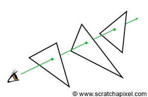
As you can see in Figure 6 though, a ray may intersect several triangles. With rasterization, we solve this problem using a depth-buffer. In ray tracing, we solve this problem by simply creating a variable in the trace() function that keeps track of the closest distance between the ray origin and the intersection point while we iterate over the objects' triangles. When an intersection is found, the distance \(t\) to the triangle is tested against this variable (let's call it \(t_{nearest}\)) which is originally set to infinity (a very large number). If \(t\) is smaller than \(t_{nearest}\) then \(t_{nearest}\) is set to \(t\). At the end, when all the triangles of all the objects have been tested, \(t_{nearest}\) contains the distance to the closest triangle that the ray intersected if any (we will need to access this triangle again at the shading stage, so we also store some information about that triangle such as the object it belongs to as well as its index in that object's triangle list).
We will talk about rays in more detail in the next lesson, though let's just say that a ray is defined by its origin and its (normalized) direction. Then the distance \(t\) defines the distance from a point along the ray to the ray's origin. The 3D position of this point on the ray can be found using the following code:
Vec3f P = rayOrigin + t * rayDirection;
 bool trace(
    const Vec3f& rayOrigin, const Vec3f &rayDirection,
    const Object* objects, const uint32_t &numObjects,
    uint32_t &objectIndex,
    uint32_t &triangleIndex,
    float &tNearest
)
{
    tNearest = INFINITY;  //initialize to infinity
    bool intersect = false;
    for (uint32_t k = 0; k < numObjects; ++k) {
        for (uint32_t n = 0; n < objects[k].numTriangles; ++n) {
            float t;
            if (rayTriangleIntersect(rayOrigin, rayDirection, objects[k].triangles[n], t) && t < tNearest) {
                objectIndex = k;
                triangleIndex = n;
                tNearest = t;  //update tNearest with the distance to the closest intersect point found so far
                intersect |= true;
            }
        }
    }

    return intersect;
}
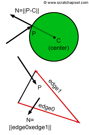
At the shading stage, we will need to access some information about the topology of the surface at the intersection point, such as the position of the intersection point itself (generally denoted P), but also the normal of the surface at the intersection point (the surface orientation which is generally denoted N) as well as its texture coordinates (the st or uv coordinates). Other quantities may be needed such as the surface derivatives at the intersection but this is an advanced topic. Finding the normal of the surface at the intersection point is often simple. For triangles, we just need to compute the cross product between two edges of the intersected triangles. For spheres, if we know the position of the sphere centre (let's call it C), we just need to compute the vector ||P-C||. More information on this topic can be found in the next lessons.
Shading

Even though ray tracing has a high computational cost compared to other approaches such as rasterization, it also has advantages that make it far more appealing than other rendering techniques. This is particularly true when it comes to shading.
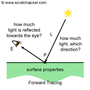
Once we found the object that a ray intersects, we then need to find out what the color of the object is at the intersection point. The color of objects or their intensity generally varies greatly across the surface of any object. This is due to changes in lighting as well as the fact that the texture of objects changes across their surface. The color of an object at any point on its surface is "just" the result of the way the object returns or reflects light that impinges on its surface towards the observer. The color at the intersection point depends on:
-
How much light (in the real world the concept of light color and intensity are one and the same) impinges on the object's surface (at the intersection point but also away from the point if the surface is transparent or translucent but that is an advanced topic).
-
The direction of that light.
-
The property of the surface itself, notably it's color.
-
The observer position. Most surfaces don't reflect light equally in all directions. Thus the amount of reflected light is likely to change with the camera or observer's position.
We will review this process in detail when getting to the lessons on shading. For now, all we want you to note is that besides the property of the object (such as its color), shading has very much to do with "gathering" information about light that falls on the object's surface. In nature, this process can be described as "light rays" emitted from light sources (or indirectly by other surfaces in the scene that reflect light rays of light sources towards other surfaces, a process known as indirect lighting), falling on the surface of objects and being reflected into the scene. Some of these reflected rays will hit more surfaces and will be reflected again in turn. Other rays, might reach the observer's eyes or the camera. In the real world, light travels from light sources to the eye (Figure 8). Though in ray tracing we generally choose to trace the path of light rays back from the eye to the surface, and then from the surface to the light source, a process which we call backward tracing because it follows the natural propagation of light backward (Figure 9).
In an obvious approach to ray tracing, light rays emanating from a source are traced through their paths until they strike the viewer. Since only a few will reach the viewer, this approach is wasteful. In a second approach suggested by Appel, rays are traced in the opposite direction -- from the viewer to the objects in the scene." An Improved Illumination Model for Shaded Display. Turner Whitted, 1980.
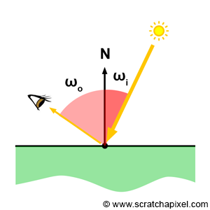
We won't explain how shading works in this chapter or this lesson, though we will provide some information about light transport algorithms in the next chapter. The function of a light transport algorithm is to simulate the way light (in the form of energy) is distributed through the scene. How a given material reflects this light into the environment, is defined by a mathematical model, or illumination model in computer graphics (if you heard the term BRDF before this is more or less what the role of that BRDF is). The Phong model (which is well known) is an example of an illumination model. Illumination models are generally implemented in what we call shaders. Shaders are generally implemented as some sort of function that takes as input the incident light direction \(\omega_i\) (the Greek letter omega) and intensity, the direction from which the material is looked at \(\omega_o\), and return based on the material properties and the illumination model being used, the amount of incident light that is reflected in the direction \(\omega_o\).
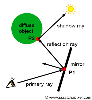
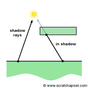
Again, don't worry too much about shading, light transport algorithm, shaders, BRDFs, and illumination models for now. All these concepts will be explained in detail in the lessons on shading. What is important to note in the context of this lesson, is that shading involves simulating the way light energy is distributed through the scene. One of the most natural ways of looking at this problem is in terms of light rays. For example, we may want to follow the path of a light ray that is emitted by a light source, then reflected by a diffuse object towards a mirror, and then finally reflected by this mirror towards the eye. Since in CG we prefer to use backward tracing, we would follow the path of that light ray the other way around. We would trace a light ray from the eye to the mirror, then cast a reflection ray (the direction of a reflection ray can easily be computed using the well-known reflection law which we will study in the lessons on shading). This ray would intersect the diffuse object. We would finally cast a ray from the diffuse object to the light. All the rays we cast after the primary rays (the ray from the mirror surface to the diffuse object and the ray from the diffuse object to the light) are called secondary rays. Secondary rays often have names of their own: for example, the ray cast from the mirror is called a reflection ray, and the ray cast towards the light is called a shadow ray. The main goal of this ray is to find if the point on the diffuse object is in the shadow of the light (if the shadow ray intersects an object on its way to the light, then the point is in shadow).
Note that each one of these secondary rays involves computing the visibility between two points. For example, when we cast a reflection ray from the mirror into the scene, we want to compute the first visible surface that the reflected ray will eventually intersect (which in our example is the diffuse object). When we cast a shadow ray, we want to find if this shadow ray intersects another object before reaching the light. And the easiest way of computing visibility between two points, as you can guess, is of course to use ray-tracing.
Ray-tracing has always been known for being the best solution to generate photo-realistic images of 3D objects, though keep in mind that until recently (up to the late 1990s early 2000s), the technique itself was considered way too expensive for being used in anything else than some research projects. Keep in mind also that computer resources increased but that the complexity of the scenes that are being rendered increased as well. Thus the actual time it takes to render these scenes hasn't changed much over the years. This effect is known as Blinn's law.
In conclusion, we can say that any light transport algorithm that requires the heavy computation of visibility (such as when reflection or shadow rays are cast into the scene) is likely to be more efficient with raytracing. Q.E.D. (_quod erat demonstrandum_, meaning "which had to be proven").
Ray-Tracing: the Challenges
Ray-tracing is very simple in its principle and "easy" to implement. The most complicated part of the process is to write code or routines to compute the intersection of rays with objects. This problem is often solved using either geometric or analytical solutions, both imply a lot of mathematics. The main issue though besides the maths is that computing these intersection tests is also often an expensive process. Though despite this main disadvantage the technique is elegant in its simplicity and makes it possible to solve both visibility and shading in one unified framework.
When we say ray tracing is easy to implement, we should probably precise though that developing a production ray tracer is a very complex task. Implementing a basic prototype is simple but making the technique robust so that it can be used in a large production, is a very challenging problem. A production ray tracing needs to support many features such as displacement, motion blur, programmable shading, etc. Many of these features are hard to get working efficiently in ray tracing. Ray tracing comes with a whole set of problems the rasterization algorithm doesn't have. These problems are difficult to solve efficiently. One of the main problems with ray tracing is that it requires all the scene geometry to be stored in memory while the image is being rendered. This is not necessarily the case with rasterization: once we know that an object won't be visible anywhere else on the screen we can throw it away (and remove it from memory). Triangles facing away from the camera can also be thrown away if back-face culling is on. In ray tracing, even if an object is not visible in the scene, it might cast shadows on over objects visible by the camera, and thus need to be kept in memory until the last pixel in the image is processed. With production scenes containing millions of triangles, the amount of memory that is required to store the data can become a problem.

The ray-intersection step as mentioned in this lesson is the most expensive part of the rendering process in ray tracing. Making the ray-geometry routine fast is generally not enough. Ray-tracers use what we call acceleration structures to speed up the process. Acceleration structures are spatial structures used to "sort" the geometry in space to avoid having to test all the objects in the scene for each cast ray. Acceleration structures won't be studied in this introduction on rendering, but you will find lessons on the topic in the ray-tracing advanced section. They work well and help to speed up ray tracing by a great factor but they also use a lot of memory which adds up to the memory that is being already used to store the geometry.
Finally, you also need to store information related to the motion of objects. This increase even further the amount of memory needed to store the scene data. All in all, ray tracers generally use for the same scene and far more memory than a rasterizer. Ray-tracing is useful to produce a more realistic images but at the expense of being slower and using more memory than a program based on the rasterization algorithm. The algorithm is simple conceptually, but very hard to get working reliably and efficiently on very large and complex scenes with complex shading.
Ray-Tracing on the GPU?
The ray-tracing algorithm was first successfully ported on the GPU in the mid-90. Quite a lot of research has been made in this area, though the ray-tracing algorithm is not yet natively supported by most consumer graphics cards (hardware to accelerate ray-tracing has been around for a very long while). GPUs will likely support ray-tracing natively in the years to come. Though as mentioned above, it needs to overcome issues such as memory management, etc. which as you know with ray-tracing is a more difficult problem than with rasterization.