Learn reading 3D model data from OBJ format files.
Reading time: 29 mins.Prerequisite
If meshes are unknown or even vaguely known to you, I strongly recommend reading the lesson Introduction to Polygon Meshes. It delves into various ways in which the data defining a poly mesh and the different flavors of poly mesh you may encounter are used when dealing with real-time GPU 3D API and, more generally, any type of software that needs to work with mesh data.
What is the OBJ File Format?
Before we move on to the next lesson, which will focus on navigating through 3D scenes, it's important to first learn how to load meaningful geometry into the scene. Up until now, we've primarily rendered simple shapes like a few triangles or used our special custom tools to make geometry loading easier, in order to keep the sample code simple. However, this approach has its limitations, as we've had to write custom code to export models from software like Maya or Blender into a unique custom format. This method is not very portable. If you want to use the same code but test it with your own models, we need a more generic solution.
This is where 3D formats come into play. However, before we dive deeper, temper your expectations. Keep in mind that ray tracing is slow due to the current limitations of computers, and without special optimizations, we'll be limited to rendering very simple models if we aim for decent render times. Considering that, in the next lesson, we will need to render the scene at interactive frame rates, we'll be restricted to using very simple models, maybe just around a hundred triangles. That's not a lot.
But don't lose hope. Firstly, being able to do this is a significant step in your journey towards mastering CG programming. Secondly, it means that future lessons will focus on how we can accelerate this rendering process as much as possible. Eventually, we will be able to render more complex scenes, and being able to easily load any model will make the experience richer and more enjoyable.
So, before we explore different strategies to accelerate rendering with ray tracing, let's go through these two lessons: loading a model using an industry-standard file format and navigating with a 3D camera. Regarding 3D file formats, there are quite a few that have been developed over the years, and among them, a handful have become very popular, or industry standards. The most famous are OBJ (also known as the Wavefront OBJ file format), glTF, and FBX. These formats are popular because they are either old, simple, and cover most of what is needed to render 3D scenes. OBJ is the simplest file format and will be the focus of this lesson. It's also one of the oldest. Before we delve deeper, it's important to understand how it differs from the other two. OBJ is simpler, primarily because it doesn't support animation and has limited support for describing material properties of objects. Both glTF and FBX support animation (including animation caches) and materials, including textures, making them popular among video game content creators and developers.
Despite its limitations, OBJ is still widely used and popular because of its simplicity. However, this simplicity is somewhat deceptive. Most people, and this will be the case in this lesson, only use and know about a fraction of what the format is capable of. Primarily, it is used to store and parse mesh geometry, that is, objects made out of polygons. But the OBJ format is quite complex and can support a wide variety of surfaces, including patches, Bezier, NURBS curves and surfaces, which are almost forgotten by those in the animation industry, though still very much in use in the CAD industry. It also supports features like bevels, levels-of-detail, trimming, and much more. Nonetheless, in this lesson, we will focus on using the OBJ format to read polygonal models, as do most users.
It's worth noting that most 3D applications, and even 2D software that supports some form of 3D rendering, support OBJ due to its simplicity and popularity. This includes software like Maya and Blender, but also Photoshop and applications like Roblox Studio, which allow you to export a level to OBJ (naturally, without any kind of animation).
Final notes before moving forward:
-
Yes, there are more formats, but they are definitely more complex. For example, USD, which we will discuss in the future, is a format developed by Pixar with the ambitious goal of being a universal scene description format. Alembic is another interesting format designed to let you export animation in the form of animation caches. Each vertex of your moving characters, let's say, is baked in frame by frame. This allows for baking an animation with the deformers applied. FBX can also let you export animation to caches.
-
Software like Maya or Blender stores its scene data in its own proprietary formats.
-
Writing an importer and exporter is often a challenging task. Creating a good one is even harder.
-
The OBJ file format is merely a convenience. Given its age and the fact that the specifications, or at least the individuals who designed them are all gone, enjoying their retirement in Santa Barbara, most companies and developers who work with it tend to interpret it in their own way, turning it into less than a reliable interchange format. However, its simplicity and practicality largely overcome these issues.
A Bit of History
Here's a brief history: The OBJ format was designed by a company named Wavefront, founded in Santa Barbara in 1984. Wavefront acquired Explore, a software developped by a French company named Thomson Digital Image (TDI), and later, in 1995, merged with a company called Alias that had developed a tool named PowerAnimator. Wavefront's products, Explore, and PowerAnimator became the foundation of Maya, and Alias|Wavefront was later acquired by Autodesk.
The OBJ File Format
But back to our file format. The format has two interesting sources of documentation: one is on Wikipedia and another on Paul Bourke’s website. Paul Bourke is a pioneer in 3D computer graphics. Interestingly, I learned from Paul Bourke’s website that the OBJ format could also be in a binary format, which was new to me. The ASCII and binary versions are supposed to have different file extensions, .obj for ASCII and .mod for binary. As I have no recollection of ever having seen the .mod file being used (though I might simply not remember), we will focus solely on the ASCII version, which, to be honest, is the one supported by modern 3D/2D software.
There's also a document in circulation, but it tends to be buried in the Internet archives. I have copied it here for your convenience. This document comes closest to what would be the specifications for the format, though it doesn't seem to be fundamentally different from Bourke's page.
As mentioned, the file extension is .obj, and the format is ASCII, meaning it can be read and edited with a standard text editor. This accessibility is one of the reasons people like it.
Now, let's look at an example:
[Example omitted]
You will see a series of lines each starting with a different letter:
-
vindicates the start of a vertex definition, naturally followed by 3 floats. -
vnindicates the start of a normal definition, also followed by 3 floats. -
vtindicates texture coordinates (s or uv coordinates), followed by 2 floats. -
findicates the definition of a face.
v, vn, vt are straightforward. Note that only v is strictly necessary and expected. If normals are defined, they can always be computed from the vertex and face data. Texture coordinates are optional as well.
f is a bit more involved. In the simple case, f defines a single face or polygon in the mesh, requiring at least 3 integer values. These values can be negative, but in this lesson, we'll only consider positive indices (we'll explain negative indices later). If f is followed by 4 integers, then the face is defined by 4 vertices. And so on. These integers are indices into the vertex array read prior to the face data.
When normal and texture coordinates data are present, we need to define which indices to use for these additional arrays in the face definition, as follows:
-
f v1 v2 v3 …: This face only uses vertex data. -
f v1/vt1 v2/vt2 v3/vt3 …: This face defines indices for both the vertex and texture coordinates arrays. -
f v1/vt1/vn1 v2/vt2/vn2 v3/vt3/vn3…: This example includes vertex, texture coordinates, and normal indices.
Indices in their respective arrays are separated by the / character.
There's also a syntax for faces using vertex and normals (but not texture coordinates):
-
f v1//vn1 v2//vn2 v3//vn3…
In principle, this is straightforward. In practice, parsing can present minor difficulties, but nothing insurmountable.
The only bit of information we need to know to get started is that comment lines start with a #, and we will ignore those when reading OBJ files. Most software also supports the definition of basic material properties using an external .mtl file, but we will ignore this for now as well. Finally, the one additional tag we will consider is g, which helps define groups. Let's see an example:
v 0.000000 2.000000 2.000000
v 0.000000 0.000000 2.000000
v 2.000000 0.000000 2.000000
v 2.000000 2.000000 2.000000
v 0.000000 2.000000 0.000000
v 0.000000 0.000000 0.000000
v 2.000000 0.000000 0.000000
v 2.000000 2.000000 0.000000
# 8 vertices

g front_cube
f 1 2 3 4
g back_cube
f 8 7 6 5
g right_cube
f 4 3 7 8
g top_cube
f 5 1 4 8
g left_cube
f 5 6 2 1
g bottom_cube
f 2 6 7 3
# 6 elements
In this example, each face is placed into its own group. You might think that these would define the hierarchy of the objects or their names, but don't rely on this assumption at all. In fact, as I will speak about in more detail in the code section, what this group definition is used for and how it should be used is unclear, even (or especially, should I say) after reading the docs. So again, as explained later, we will merely use the tag g as an indicator of whether we should split the geometry defined in the file into several possibly independent pieces or objects. And that's all.
When exporting several objects into an OBJ file, exporters often define each object as a series of vertices (which may include texture coordinates and normals), followed by face indices, then another group of vertices and face indices, and so on. This essentially mirrors the type of hierarchy seen in the DCC tool outliner or scene graph editor.
While discussing this topic, it's noteworthy that the OBJ format, unlike FBX or other formats such as Alembic, does not allow you to define transformations that could be applied to the geometry. This means any transformations applied in software like Maya or Blender are baked into the vertex positions upon exporting the meshes, resulting in the loss of those transformations in the OBJ file.
g group1
v …
v …
…
f …
f …

g group2
v …
v …
…
f …
f …
This is how you will typically see 3D scenes exported to OBJ files. And this "flavor" of the format will be our focus for the importer. Before we dive into some code, there are a few important things you need to know about the format. Consider these examples:
g group1
v …
v …
v …

f 1 2 3

g group2
v …
v …
v …

f 4 5 6
f 1 5 6
v …
v …
v …
v …
v …
v …

g group1
f 1 2 3

g group2
f 4 5 6
f 1 5 6
They essentially define the same geometries; however, in the first case, we declare some vertices, then some faces, then additional vertices, and then more faces. In the second example, all vertices are declared together, followed by the face definitions. The useful things to know are:
-
OBJ uses 1-based index values. The first index in the vertex list is number 1, not 0. Since C/C++ uses 0-based index arrays, we will need to subtract 1 from all index values read from the file.
-
Any face definition can reference any vertex as long as it has been defined prior to the face definition. So, the index value effectively refers to the position of the vertex as the vertices are read from the start of the file. If you look at the first example, the second group includes two faces, the first of which references the vertices that were defined prior to the group definition (indexes 4, 5, and 6, not 1, 2, and 3 as one might think), and the second (
f 1 5 6) references the very first vertex of the file. -
This is where negative indices come into play (though, as mentioned, we won’t be using them). When negative indices are used, the index values correspond to the vertices starting from the face definition position in the file backward. Here is an example to clarify:
g group1
v …
v …
v …

f 1 2 3

g group1
v …
v …
v …

f -3 -2 -1
f -6 -2 -1
In other words, you reference the vertices in reverse order, where -1 indicates the last vertex read from the file at the time the face definition was made. Time to code.
Code Discussion
Regarding the code, to be honest, we won't delve into too many details. First, writing a parser is not so much about algorithms but more about programming itself. It's not Scratchapixel's objective to solely teach programming. Furthermore, I encourage you to search the web and GitHub, as many implementations of OBJ readers exist. Understanding the format and reviewing different implementations can be very enlightening. Parsing file formats can be complex. A common strategy involves using lexer/parser libraries, which allow you to define the rules of your format. The libraries then generate code that reads file content according to these rules, including managing syntax errors. However, this doesn't necessarily simplify the process, as getting these tools to work can be as challenging as writing the parser yourself.
I won't discuss what lexical analyzers (lexers) and parsers are in this lesson, nor will I detail the libraries mentioned earlier, like Flex and Bison. I'll leave it to you to explore these on your own. It's worth noting that parsers are more relevant for ASCII formats. With binary formats, parsing is not required, though you still need to understand the file's data organization. The OBJ format, being ASCII-based, is simple enough that a parser might not be necessary or even feasible. Its structure allows for quite flexible data organization, which can complicate automated parsing. For example, we've shown data can be organized in different ways within the same file, challenging the definition of strict parsing rules.
Regardless, due to the format's simplicity, we'll develop our logic to read the data. This implementation focuses on:
-
Simplicity and brevity: Our goal is to create an example as concise as possible, utilizing the C++ standard library functions extensively. Very certainly, our implementation is not robust nor the fastest possible implementation you can come up with, but it has the benefit of being extremely compact and simple, which is in line with Scratchapixel's teaching philosophy: no libraries, one single self-contained app that can be compiled from the command line.
-
Implementing only the necessary features: We aim to read the various objects defined in the file, their vertices, normals, and texture coordinates, if available. In this lesson's version, we'll overlook materials and the hierarchy of objects since our goal is rendering, where object hierarchy is less pertinent. Had the OBJ format included transformations (e.g., via matrices), the hierarchy would be significant. However, as it stands, we don't need to address hierarchical transformations.
Here is the code we'll be using. Take a look, and I'll explain some noteworthy aspects:
struct FaceVertex {
	int vertex_index{-1};
	int st_coord_index{-1};
	int normal_index{-1};
};

void ParseFaceVertex(const std::string& tuple, FaceVertex& face_vertex) {
	std::istringstream stream(tuple);
	std::string part;

	std::getline(stream, part, '/');
    assert(!part.empty());
	face_vertex.vertex_index = std::stoi(part) - 1;

    if (std::getline(stream, part, '/') && !part.empty()) {
        face_vertex.st_coord_index = std::stoi(part) - 1;
    }

    if (std::getline(stream, part, '/') && !part.empty()) {
        face_vertex.normal_index = std::stoi(part) - 1;
    }
}

void ProcessFace(const std::vector<std::string>& tuples,
				 std::vector<FaceVertex>& face_vertices) {
	assert(tuples.size() == 3);
	for (const auto& tuple : tuples) {
		FaceVertex face_vertex;
		ParseFaceVertex(tuple, face_vertex);
		face_vertices.push_back(face_vertex);
	}
}

std::vector<Vec3f> vertices, normals;
std::vector<Vec2f> tex_coordinates;

struct FaceGroup {
	std::vector<FaceVertex> face_vertices;
	std::string name;
};

/**
 * Avoid using std::vector for storing elements when we need to maintain
 * stable pointers or references to those elements across insertions or
 * deletions. This is because the underlying storage of a std::vector may
 * be reallocated as it grows, potentially invalidating existing pointers
 * and references. To ensure that pointers and references remain valid
 * despite container growth, use std::deque or std::list instead, as these
 * containers provide stable references even when new elements are added
 * or existing elements are removed.
 */
std::deque<FaceGroup> face_groups;

void ParseObj(const char* file) {
	std::ifstream ifs(file);
	std::string line;
	face_groups.emplace_back();
	FaceGroup* cur_face_group = &face_groups.back();
	while (std::getline(ifs, line)) {
		std::istringstream stream(line);
		std::string type;
		stream >> type;
		if (type == "v") {
			Vec3f v;
			stream >> v.x >> v.y >> v.z;
			vertices.push_back(v);
			if (cur_face_group->face_vertices.size() != 0) [[unlikely]] {
				face_groups.emplace_back();
				cur_face_group = &face_groups.back();
			}
		}
		else if (type == "vt") {
			Vec2f st;
			stream >> st.x >> st.y;
			tex_coordinates.push_back(st);
		}
		else if (type == "vn") {
			Vec3f n;
			stream >> n.x >> n.y >> n.z;
			normals.push_back(n);
		}
		else if (type  == "f") {
			std::vector<std::string> face;
			std::string tuple;
			while (stream >> tuple)
				face.push_back(tuple);
			ProcessFace(face, cur_face_group->face_vertices);
		}
		else if (type == "g") {
			if (cur_face_group->face_vertices.size() != 0) {
				face_groups.emplace_back();
				cur_face_group = &face_groups.back();
			}
			stream >> cur_face_group->name;
		}
	}
	std::cerr << face_groups.size() << std::endl;
	for (const auto& group : face_groups) {
		std::cerr << group.name << " " << group.face_vertices.size() / 3 << std::endl;
	}
	ifs.close();
}

void DoSomeWork() {
	...
	for (const auto& group : face_groups) {
		for (size_t n = 0; n < group.face_vertices.size() ; n += 3) {
			const Vec3f& v0 = vertices[group.face_vertices[n].vertex_index];
			const Vec3f& v1 = vertices[group.face_vertices[n + 1].vertex_index];
			const Vec3f& v2 = vertices[group.face_vertices[n + 2].vertex_index];
		}
	}
	...
}

int main() {
	ParseObj("./zombie.obj");
	DoSomeWork();
	return 0;
}
Note that the code does show how to both read the data from an OBJ file using ParseObj, but also how the data is being used later on in the function DoSomeWork() to utilize the read data (here looping for all the objects in the file and for each object looping through each triangle).
Ah yes, something really important. In this example and the next lessons, we will assume that all the geometry that has been exported to the OBJ file has been triangulated. The sample code above does not support geometry with polygons of arbitrary size (with more than 3 vertices). As we want to move quickly throughout the development of the sections 2, we will revise this lesson later to integrate this element once it becomes necessary.
But the crux of the code is that we do store all vertices, normals, and texture coordinates into their respective arrays. So even though we may have 2 or more objects in the scene, they will all reference the same vertex array, for instance.
Our code works because we assume it was properly formatted when exported to start with. The code itself is not robust for production use as it doesn't check things such as whether a vertex declaration does effectively have 3 floats and 3 floats only. Any declaration can expand on more than 1 line and this is also something we don't check. Again, we assume in this example that the data we are reading is properly formatted.
Now we read the file line by line and convert the string into a std::istringstream. While this is not super fast (but unless you deal with very large 3D scene files reading time is not something you should worry too much), it has the benefit of making things such as reading tokens whether string or numbers super easy. For example, we can write:
std::istringstream stream(line);
std::string type;
float x, y, z;
stream >> type >> x >> y >> z; // to read v 0.134 0.125 -0.436
And that's super cool. No need to use extract the tokens ourselves check whether this is a valid float, convert the string into a float, etc. Of course, if you like that kind of stuff, feel free to implement this that way. Some OBJ implementations that you will find yourself on GitHub even implement their own string to float function ensuring it's fully IEEE-754 standard. Good luck with that.
So using that process we can define if the line starts with either a v, vn, vt, f, or g, which are the only tags we will process for now (ignoring everything else). This is also super simple.
The only bit that's a bit more work-intensive is the part where we read the face data. That's because we need to take into consideration whether the face definition includes data for the normal and or the texture coordinates in addition to the vertex itself. What we do when we encounter the f tag is read every space separating string that we find after the tag itself and store them in a vector. We call these strings tuple because they can effectively represent either one (vertex), two (vertex and normal or texture coordinates) or three indices (vertex texture coordinates and normals). We then pass the list of "tuples" to the ParseFaceVertex() method that will loop through each one of these tuples and extract the data accordingly depending on whether tuples have 0, 1, or 2 forward slashes (/). Now here again, this is not production-ready code, as if it was, we would put plenty of guards to be sure the data is properly formatted and consistent. For example, if we find that one tuple has 2 slashes while all the other tuples for the current object we are parsing had only 1, we should probably raise an error. Similarly, attempting to use normals or texture coordinates with no data for those should also be flagged..
We store the indices for the vertex and potentially the normals and texture coordinates into a structure called FaceVertex. We have one FaceVertex instance per vertex in the object. And we store them all in the face_vertices list of the current object. Since we are only dealing with triangulated meshes for now, we know we should have 3 and only 3 of such tuples per face declaration. Reconstructing the triangles is also simple. First the size of every face_vertices list should be a multiple of 3. That's an easy check. Then you loop through the face_vertices list and each group of 3 consecutive elements in the list forms the indices of a triangle.
Finally, as we want to keep the objects separate, we will store the face_vertices into a structure called FaceGroup and maintain a list of those (face_groups).
Sure, here's the revised text with the correct usage of � for inline code formatting:
Now, the usage of the g tag is not precisely clear, and despite references from Paul Bourke and Wikipedia, it seems that the specifications regarding its exact initial intentions are missing. The g tag can itself be followed by one or more strings. Each string defines the name of a group to which the subsequent geometry belongs. For instance, g cube front would signify that all faces defined after the g tag belong to both the cube and front groups. Interestingly, exporting a cube from Maya where the faces of the cube are individual quads organized as follows:
cube
 |-polySurface1
 |-polySurface2
 |-polySurface3
 |-polySurface4
 |-polySurface5
 |-polySurface6
Gives:
g cube polySurface1
...
g polySurface2 cube
...
g polySurface3 cube
...
g polySurface4 cube
...
g polySurface5 cube
..
g polySurface6 cube
As you can see, the order of the groups for the first line is different from the order used in the next consecutive line. Unless there's a logic there that we are not aware of, this means we can't rely on the order of the groups to discern the object's tree structure (nor their names). So, while one could potentially devise a rule to recreate some hierarchy by examining the groups all objects have in common and so on, even that wouldn't guarantee the reconstruction of the object tree structure as it existed in the original scene the file was created from. For now, all we can determine is that these are just the names of the groups that the subsequent geometry belongs to. But why Maya mixes the names is a mystery... (and Blender doesn't do much better).
Furthermore, note that multiple vertex-face definitions could follow a g declaration. According to Bourke's document, all objects defined after a g declaration should belong to the same groups. However, how precisely that g should be used is not very clear from what we can glean from the remaining docs. If you happen to know or are retired from Wavefront, do let me know.
In summary, we will establish our own rules (as everyone else does), and we will assume that g is employed to delineate the various objects stored in the file. Thus, we will consider a g tag as indicating the start of a new object. Additionally, if two consecutive face declarations are separated by a declaration of vertices, then each group of face data defines a separate object. Although there exists an o tag for storing the names of objects, Maya doesn't seem to export those and instead uses the g tag to export the object names alongside all the groups they were grouped under. Sigh! This is why we mentioned earlier that it's not necessarily straightforward to use an automatic parser such as Lex/Bison to handle the task, and why essentially people take liberties with the way the OBJ file format operates and how they interpret the data within the file. In other words, everybody has their own interpretation of it.
Returning to the problem at hand: every time we encounter a g tag, we will add a new group to a list of FaceGroup called face_groups, and any further vertex declarations will then be added to the face_vertices list of that group (special care needs to be taken when dealing with the initial group, which technically should be called default). As you can see by looking at the code, FaceGroup is a structure that includes a list of FaceVertex and a name (std::string).
Additionally, we need to consider the case where the start of a new object is not declared with the use of the g tag, which the exporter might simply omit. So, if the current face group already contains faces and we start to read a vertex, then we can reasonably deduce that we are probably reading the data for a new object. When this happens, we create a new group, append it to face_groups, and continue the process of reading the file by appending all further data (vertices, normals, texture coordinates, face data) to that new group.
Note that because g flags might not be written by the exporter into the file, we need to start reading the vertex data with a FaceGroup instance on hand. That's why we need to create one before we start reading the content of the file.
That's about it really. One important thing from a programming point of view is that we are keeping a pointer to the new group in the cur_face_group variable. That's why face_groups is defined as std::deque and not as a std::vector. In C++, the address of an element in a vector is not guaranteed to stay the same as the list potentially grows or shrinks (due to internal reallocation processes). For this reason, to get consistent pointers to elements making up the face_groups list we need to use std::deque (or std::list also a possible choice) which doesn't suffer from this fatal issue.
Future Development
-
Add support for polygons of arbitrary size.
-
Add support for materials.
Testing the Code
Since it's too complicated to write code using a real-time 3D API such as Vulkan to render the content of our file (a basic Vulkan view requires more than 1000 lines of code), we will stick to rendering our geometry using ray-tracing, which, as you know, is super simple to implement but slow. As this is not a lesson on ray tracing, and considering that all the code we are using in the example for rendering the geometry is explained in various lessons of section 1, we will not spend any time on this. As a refresher and just to show you how we use our vertex and normals arrays to intersect the rays with the triangles making up the objects and to shade the hit points, we will paste the code here:
void DoSomeWork() {
	auto start = std::chrono::high_resolution_clock::now();
	const Vec3<float> ray_orig(0,0,12);
	float aspect_ratio = image_width / static_cast<float>(image_height);
	float scale = std::tan(DegreesToRadians(0.5f * angle));
	auto buf = std::make_unique<uint8_t[]>(image_width * image_height);
	uint8_t* pbuf = buf.get();
	std::memset(pbuf, 0x0, image_width * image_height);
	for (uint32_t j = 0; j < image_height; ++j) {
		float y = (1 - 2 * (j + 0.5f) / static_cast<float>(image_height)) * scale * 1 / aspect_ratio;
		for (uint32_t i = 0; i < image_width; ++i, ++pbuf) {
			float x = (2 * (i + 0.5f) / static_cast<float>(image_width) - 1) * scale;
			Vec3f ray_dir(x, y, -1);
			ray_dir.normalize();
			float t = super_far;
			for (const auto& group : face_groups) {
				for (size_t n = 0; n < group.face_vertices.size() ; n += 3) {
					const Vec3f& v0 = vertices[group.face_vertices[n].vertex_index];
					const Vec3f& v1 = vertices[group.face_vertices[n + 1].vertex_index];
					const Vec3f& v2 = vertices[group.face_vertices[n + 2].vertex_index];
					Hit hit;
					intersect(ray_orig, ray_dir, v0, v1, v2, hit);
					if (hit.t < t) {
						t = hit.t;
						const Vec3f& n0 = normals[group.face_vertices[n].normal_index];
						const Vec3f& n1 = normals[group.face_vertices[n + 1].normal_index];
						const Vec3f& n2 = normals[group.face_vertices[n + 2].normal_index];
						Vec3f nor = n1 * hit.u + n2 * hit.v + n0 * (1 - (hit.u + hit.v));
						nor.normalize();
						*pbuf = static_cast<uint8_t>(255 * std::max(0.f, nor.z));
					}
				}
			}
		}
		fprintf(stderr, "\r%03u", static_cast<uint32_t>(j / static_cast<float>(image_height) * 100));
	}
	auto stop = std::chrono::high_resolution_clock::now();
    auto duration = std::chrono::duration_cast<std::chrono::milliseconds>(stop - start);
    std::cout << "Render time: " << duration.count() / 1000.0 << " seconds." << std::endl;
	std::ofstream ofs("./result.ppm", std::ios::binary);
	ofs << "P6\n" << image_width << " " << image_height << "\n255\n";
	for (uint32_t i = 0; i < image_width * image_height; ++i)
		ofs << buf[i] << buf[i] << buf[i];
	ofs.close();
}
The way we loop through the triangles is pretty simple. We first loop over all the groups. Then, we loop over the current group's face_vertices list to build each triangle, which is then tested for intersection with the current ray. Accessing the vertices and normals making up the current triangle using the FaceVertex vertex and normal index should be rather straightforward. We don't use texture coordinates in this example. This is left as an exercise if you wish to explore, but as we will have lessons on texturing later on, they will be used then. So, if you are not sure how to adapt the program yourself to visualize them (at least), please check the lesson on texturing.
A few additional notes:
-
We are using the U and V barycentric coordinates of the hit point to interpolate the normals that are used for shading.
-
For shading, we just take the dot product between the normal and a light that is oriented along the camera direction. In this sample code, the camera is looking down the z-axis. We did this so that we wouldn't have to deal with matrices to orient the camera in any particular direction.
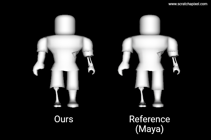
Here is the result, with our render on the left and the same model rendered in Maya on the right. As you can see, they are identical. Hooray, our importer worked. The model is an asset provided by Roblox Studio (with their courtesy). Roblox Studio is a fairly fun tool for creating your own 3D scenes, which you can export to OBJs. You can find the OBJ file alongside the source code files on the website's GitHub repo.
Note that while this model has roughly 3700 triangles only, it already takes 12 seconds to render on a 3.6GHz single-core processor. Ouch! That's huge and certainly way too much for our next lesson, which is about 3D navigation controls. In order to navigate through the scene, we will need at least to achieve an interactive framerate, ideally no lower than 30 fps. So obviously, we will need a much "smaller" model to make this work. Naturally, this is slow because we don't use any of the optimizations that are typically used in production, such as using an acceleration structure, multithreading, and SIMD instructions—all topics that will be covered in the next lessons. So, patience. Note that a good 60%+ of the pixels in the image are black, and yet for each one of these pixels, we test the 3700 triangles of the model for intersection. Even with something as simple as a ray-bounding box test, we could already significantly decrease that render time.
Trivia: 12 seconds is not that absurd. With an image size of 640x480 pixels and 3700 triangles tested for each pixel, assuming an average of 50 floating-point operations for the ray-intersection test (knowing that some rays will go further in the function than others) and additional operations for the shading calculation, etc., with a 3.6GHz single processor, we get: 640x480x3700x50 / 3.6x10^9 = 15.8 seconds. So we probably have slightly fewer floating-point operations on average, but the order of magnitude is correct.
But anyway, our goal was to write a simple OBJ loader so that in the next lessons we would have a consistent and easy way of loading various models for testing. That part is achieved and can be checked off our TODO list. Let's move on.