Creating, Saving and Reading Digital Images
Reading time: 28 mins.What is a Digital Image?
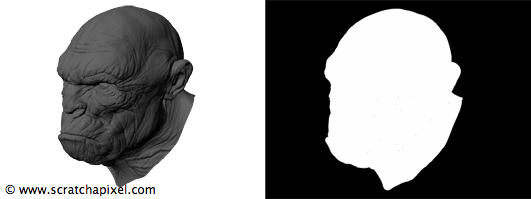
Before we learn about storing the result of a 2D digital image to a file, let's first have a look at what a digital image is. Sometimes digital images are black and white (B&W) but most of the times they are in color. We learned in the previous lesson that in order to represent a color, computers need three values (of couse we only need one value for B&W images) which are, in the additive color system, the primary colors red, green and blue. For computer generated images, we usually store a fourth value which is called the alpha channel or the mask of the image. This mask or alpha channel is used to represent the opacity of the objects from the rendered scene. For opaque objects, this value should be 1 and for fully transparent objects (or where there is no object at all) this value should be 0\. If the value is somewhere in between, then we deal with a semi-opaque object. The following figure shows an example of such images and its associated alpha channel or mask. Later in this chapter, we will show what it is used for.
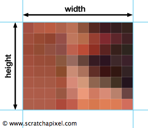
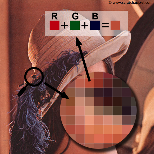
To summarise, we know that when we deal with computer generated images, we need three values to represent a color and potentially one additional value to store the object opacity (that is when we render a 3D scene). Now that we know about color let's have a look at the digital image itself. A digital image (which is also sometimes called raster graphics or bitmap), in its simplest form, is just a two dimensional array of pixels (pixel stands for picture element). Its dimension is defined by the number of pixels that are along the width of the image (columns) and the number of pixels that are along its height (rows). A pixel can be seen as a square to which we assign a color as showed in figure 2 and 3 (however a pixel is not a little square. More formally it represents a sample. You will find more information about this at the end of this chapter). When we very closely look at a digital image on the screen, we can see the individual pixels composing it. However, from the distance, the fact that the image is made of individual discrete pixels is indistinguishable to the human eye.
To create a digital image, we need to create a two-dimensional array of pixels where each pixel stores three values (or four for computer generated images) which as explained above, are used to encode the pixel's color. Usually, we denote these three values with the acronym RGB (for red, green and blue) or RGBA (for red, green, blue and alpha) if the image also stores an alpha channel.
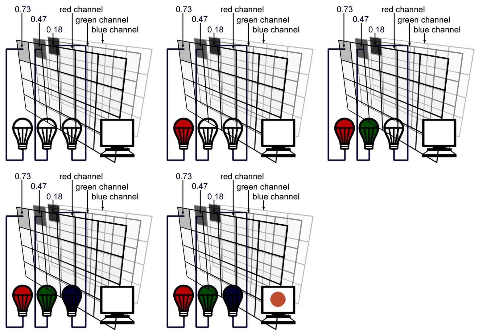
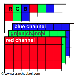
Note that we can also store all the values for the red light in one two-dimensional array and do the same for the green and blue light as in figure 4 and 5\. Each two-dimensional array is called a channel. In most viewing programs (for instance in Photoshop), image channels can be seen independently from each other. They are usually visualised as a black and white image because they each encode the amount of red, green or blue light that each pixel from the image is made of.
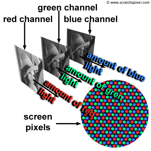
We learned in the previous lesson that each screen pixel is composed of a small red, green and blue light. Switching these three lights at the same time to their maximum intensity would result in a white dot on the screen. Finally each pixel in the image will correspond to one pixel on the screen and the brightness or intensity of each of the red, green and blue light illuminating that pixel on the screen will be determined by the red, green and blue value stored for that pixel in the image file (as illustrated in figure 5).
In a renderer, the RGB pixel values should be stored using floating-point precision. This allows us to keep as much numerical precision as we can to store, represent, and process colors in the rendering pipeline until we store the final image to disk (at which stage, we might convert the values to another type. Note that we say "we might". It doesn't have to be. If you use a 8 bpc file format where bpc stands for "bits per channel" such as JPG, TGA or PNG, then you will need to convert this floating point values to a byte or in other words, an integer in the range [0:255]). An alternative representation which is used by Photoshop is to encode pixel values using integers (round numbers) going from 0 to 255, where 0 represents no light for a particular color, and 255 maximum intensity. From a programming point of view, you can declare a color in different ways. For simplicity, we decided to save pixel data using floats (see the section below on High Dynamic Range Images).
class Image
{
public:
    Image(const int &w, const int &h) : width(w), height(h) { imageData = new float [w * h * 3]; }
    ~Image() { delete [] imageData; }
    void setPixel(const float *pixelValues, const int &x, const int &y)
    {
        imageData[(y * width + x) * 3] = pixelValues[0];
        imageData[(y * width + x) * 3 + 1] = pixelValues[1];
        imageData[(y * width + x) * 3 + 2] = pixelValues[2];
    }
    void saveToPpm(const char *filename) { ... }
    void readPpm(const char *filename) { ... }
    float *imageData;
    int width, height;
};
The class is quite simple. The constructor takes the width and the height of the image we want to create as arguments; we then allocates the necessary memory (line 6) to store the image data (the width of the image multiplied by the height multiplied by three, the number of components in a RGB color). For convenience, we creates a setPixel method (lines 12 to 17) that we can use to set the color of a particular pixel (whose coordinates x and y are passed in arguments). The code for the save() and the read() methods is given further down. These methods are used to save/read a PPM image to/from disk. The PPM file format is described later in this chapter as well.
Pixel values can be either packed as RGB or saved as three channels (three two-dimensional array). In our code, the components of a pixel color are saved sequentially in the computer's memory (that is the value B of a particular pixel follows the value G which follows the value R). You might decide to save the red components of all the pixels first followed by the green and blue values:
void setPixel(const float *pixelValues, const int &x, const int &y)
{
	unsigned pos = y * width + x;
	imageData[pos                     ] = pixelValues[0];
	imageData[width * height + pos    ] = pixelValues[1];
	imageData[width * height * 2 + pos] = pixelValues[2];
}
This choice depends primarily of the way you want to access and process the pixel data in your application later on.
Computer Number Format: Which One is Good for Images?
Storing pixel information from a computing point of view is very simple. For each pixel of the frame we need to store three numbers, the amount of primary colors this color is made of. And we need to store as many pixels as they are in a frame which we can compute from the image width and height. A more difficult choice to make is the numerical precision with which we should store these numbers? As you may know, programming languages (C++ in our case) offer different computer number formats or types which can be used to encode numbers. The simplest element is a byte which contains the 8 bits which we can use to encode the characters of our alphabet but also to represent a number from 0 to 255. Having only 256 levels to encode each channel (red, green and blue) of each pixel of an image, is not a lot even though when the red, green and blue channels are combined together this represents a possible choice of more than 1.6 million colors. The minimum difference we can encode with this system for any of the RGB component is 1 over 255 which is quite a large step. This can lead to problems; we might not be able to represent variations between colors with enough precision particularly in the low tones of the image to which the human is particularly sensitive (a problem we have described in the previous chapter).
To address this issue, we can gain more room in the lower part of the image intensity values by artificially adding a 1/2.2 gamma encoding to the pixel values (this process was described in detail in the previous chapter). The problem with this solution is that it modifies the original pixel values which are lost once this gamma encoding is applied and the gamma encoded image data saved to disk. Another problem with using a byte as the format number to encode pixel values, is that they often need to be converted from floating-point precision numbers, a problem which is known as quantization and which we discuss further down in this chapter. Despite all these issues, 8 bits RGB images are still very popular. This includes file formats such as JPG or PNG which are very common and which are de facto standards when it comes to displaying images in an internet browser. The reason of their success is mainly their file size. Using 8 bits rather than 32 bits which is needed if you use floating-point precision means you use four times less disk storage and memory to save or load the image data (for an RGB image, the total number of bits is 3*8 = 24 bits if bytes are used. Using the C++ type float we need 3*32 = 96 bits and 96/24 = 4). When these 8 bits RGB image are transferred across the internet, they use far less bandwidth than 32 bits float images. You would pay less for your bandwidth usage and would see the image appearing quicker on the screen, two advantages which are pretty appealing.
In summary, we can say that 8 bits RGB images are the most common way of storing pixel values. This is particularly true of images produced, processed, saved or read from most consumer electronics devices having anything to do with images (digital camera, TV screens, computers, etc.).
However as the network and disk technologies improve and become cheaper, using 8 bits RGB image for the internet becomes less of a necessity. Industries which are in need to produce high quality images generally prefer now image format using floating-point precision. Some intermediate formats have been developed in the 1990s such as the Kodak Cineon file format that used 12 bits. Today you can use the OpenEXR file format which almost the de facto standard in the film industry. With OpenEXR you can save images in either 16 bits (called half-float) or 32 bits. Another popular format supporting floating-point precision is the TIFF format which was originally developed in the mid 1980s (but support for floating-point encoding was added later). Such formats often rely on compression techniques to make the image file size smaller. Let's not forget the RAW format which is used by digital cameras to save out data coming from the CCD and the DPX format (Digital Picture Exchange) which is popular in the visual effects industry (more information on these formats will be available later in the 2D section).
At first the process of writing image data to a specific file format might seem like a mysterious process. And it often is, as most of the times, as a user, all you have to do is to present the data in the right form to the image format's API which is a sort of black box doing the work for you. To write your image data to a specific format you need to download and install the image format's API on your computer as well as do some complex linking or setup when you compile you program with this API's libraries. Alternatively you can directly read and write images in a specific format if you know this format specifications. In this lesson, we will show how to write and read PPM (and PFM) files which is the simplest possible file format you can almost imagine. Still, it is supported by applications such as Photoshop or Preview (on Mac) which makes it very convenient if you develop graphics applications and quickly need to read/write images. We will also show how to read and display PPM images using our own program.
The number of bits used to encode a pixel is called the color depth or bit depth of bits per pixel (bpp). The number of color that can be created increase with the number of bits. Note that with with only 1 bit we get only encode black or white. Most images nowadays use 24 bits per pixel (8 bits or 1 byte per component and there is 3 components in a pixel, R, G and B) a standard which is also know as True Color. Most image formats store the pixel components in the order R-G-B but some formats store them in the reverse order (B-G-R).
Image Quantization

In the old days, renderers usually used floating point precision to represent color but had to convert these colors to a much lower bit depth before saving them to disk. Even today most of the graphics file formats only support 24 bpp (using more bits increase the size of the file on disk). Remember that 24 bpp means that each channel of the image, or each component of a RGB pixel uses 8 bits with which we can only represent round numbers going from 0 to 255. A naive conversion from float to byte involves to clamp the original float value between 0 and 1, multiply it by 255 and assign the result to a variable of the appropriate type (byte, or unsigned char in C++ which involves a type casting).
unsigned char r = (unsigned char)(std::max(0.f, std::min(1.f, pixel[0])) * 255);
unsigned char g = (unsigned char)(std::max(0.f, std::min(1.f, pixel[1])) * 255);
unsigned char b = (unsigned char)(std::max(0.f, std::min(1.f, pixel[2])) * 255);
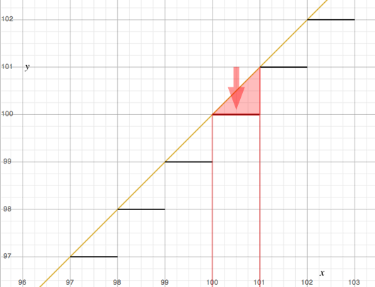
As you can see, this process reduces the precision with which we represent the pixel values. All pixel values that were for example contained in the range 100 to 101 (101 non inclusive) after being clamped and scaled up by 255 are reduced to the value 100\. In other words we reduce all the colors or pixel values contained in this range to one single color or value. This process is known as image quantization.
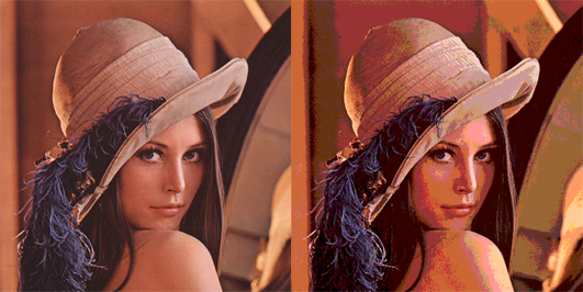
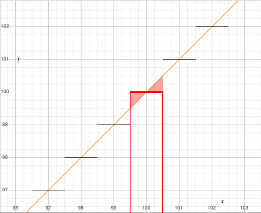
Typically, this lead to reduction of the image quality since we loose information about the image itself (the nuances of tones or colors contained in the original image data is reduced to a smaller number of values therefore a smaller number of colors). This can also be seen as a form of image compression. Image quantization introduces errors in the image (contouring) which can be reduced by using techniques such as halftoning and dithering. To keep this lesson reasonably short these techniques will be explained in a seperate one. Furthermore, image quantization is of little interest as professional image formats (TIFF, OpenEXR) support float images (32 bits per channel that is 96 bpp). However because we will present in this lesson a simple format to store images that converts the float value to a 32 bpp image, let's just mention that the basic conversion technique we have presented above can be improved. Note that all the values in the range 100 to 101 for instance are mapped to the rounded value 100 (as showed in figure 8). However the floating values greater than 100.5 are closer to 101 than they are to 100\. Consequently, a better method would consist of mapping all the values from 99.5 to 100.5 to 100 and all the values from 100.5 to 101.5 to 101\. This can be done with a slight change to the code we provided above. Once a value has been multiplied by 255 we will add an offset of 0.5 to the result before clamping it to the nearest round number. If the float value is 100.3, adding 0.5 will give 100.8 which will be cast to 100\. If the value is 100.6 adding 0.5 results in the value 101.1 which will be cast to 101.
unsigned char r = (unsigned char)(std::max(0.f, std::min(1.f, pixel[0])) * 255 + 0.5);
unsigned char g = (unsigned char)(std::max(0.f, std::min(1.f, pixel[1])) * 255 + 0.5);
unsigned char b = (unsigned char)(std::max(0.f, std::min(1.f, pixel[2])) * 255 + 0.5);
Encoding Gamma
If you save your image to a 32 bpp file format it might be useful to add a gamma encoding to your image (we have explain the advantage of using gamma encoding in the previous chapter). This can easily be done on the pixel values before they get converted from 32 to 8 bits. The following code does something similar to the sRGB color space but not quite exactly. It simply applies a 1/2.2 gamma encoding to the pixel values (converting linear pixel values to sRGB implies a slightly more complex process):
unsigned char r = (unsigned char)(std::max(0.f, std::min(255.f, powf(pixel[0], 1/2.2) * 255 + 0.5f)));
unsigned char g = (unsigned char)(std::max(0.f, std::min(255.f, powf(pixel[1], 1/2.2) * 255 + 0.5f)));
unsigned char b = (unsigned char)(std::max(0.f, std::min(255.f, powf(pixel[2], 1/2.2) * 255 + 0.5f)));
Simple Example: the PPM file format
Finally we will give an example of a very simple image format that can be read by some application such as Photoshop or Preview (on Mac). Because of its simplicity, this format is very useful for debugging graphics applications. The format is called PPM (which stands for Portable Pixmap) and is (according to its creators) the lowest common denominator image file format. We don't recommend it as a professional format but as a starting point it is perfect. In the following example we will create a float image, store some values in the pixels of this image and save the result to disk using the PPM format:
void saveToPpm(const char *filename)
{
    std::ofstream ofs;
    // binary flag is necessary on Windows
    ofs.open(filename, std::ios_base::out | std::ios_base::binary);
    ofs << "P6\n" << width << " " << height << "\n255\n";
    float *pixel = imageData;
    for (int j = 0; j < height; ++j) {
        for (int i = 0; i < width; ++i) {
            unsigned char r = (unsigned char)(std::max(0.f, std::min(255.f, powf(pixel[0], 1/2.2) * 255 + 0.5f)));
            unsigned char g = (unsigned char)(std::max(0.f, std::min(255.f, powf(pixel[1], 1/2.2) * 255 + 0.5f)));
            unsigned char b = (unsigned char)(std::max(0.f, std::min(255.f, powf(pixel[2], 1/2.2) * 255 + 0.5f)));
            ofs << r << g << b;
            pixel += 3;
        }
    }
    ofs.close();
}
This code is part of the Image class presented above. First we need to open a file for output (lines 6 to 7). We write some information about the image (which is usually called the header file). P6 defines the type of the PPM image (color 8 bap), then the width and height of the image. The third value specifies the maximum value encoded in the file (255). Finally we loop over all the pixels of the image, apply a gamma encoding to the original pixel values (if desired), multiply the result by 255, add an offset (0.5), clip the result to the range [0:255] and cast the result to a byte (unsigned char). The three components of the converted pixel color are written to disk (line 15) and we then move to the next pixel (offset of 3 floats in the image data float array. Line 16).
High Dynamic Range Images
The convention being used to define what is white on the screen is in theory completely arbitrary. In practice most computer systems though define the value 1 (R = 1, G = 1, B = 1, 1 if you deal with float or 96 bpp images, 255 if you deal with 32 bpp images) as white or as the brightest color that can be displayed on the screen. However it is possible to store values greater than 1 (assuming you use float images). Remember from the first chapter that colors is actually light and that we should differentiate the color's hue from its intensity. In a real world scene, there can be a very large difference between the brightest areas of the scene (those exposed to the light of the sun for instance) and the darkest ones (those in shadows). On a typical sunny day the ratio between these regions can be as extreme as 1 over 100000. If you use 8 bits to encode one of the tree values of a color (the red, green or blue component) the maximum number you can define is 255. In that case, the dynamic range of the image is only 1:255. File using up to 12, 14 (RAW format), 16 (half-float) or 32 bits per pixel per channel can save a greater range of luminance and are called High Dynamic Range Images (or HDRI). Colors greater than 1 can not be displayed on the screen. They will be clipped to 1\. In order to display the color which are outisde the screen's own dynamic range, we need to remap the values greater than one to a range in which they can be visualised on the screen. This process is called tone mapping. The simplest way of achieving this is to multiply the colors by a values lower than 1 but smarter tone mapping algorithms exist (we will write a lesson on this topic in the future).
Compression
Image data as we mentioned before, may take a lot of space on disk. One way of reducing an image file size is to reduce its bit depth (for exampe you can store pixel values using 8 bits per chanel instead of 32 which decrases the file size by a factor of 4). However as we explained in the part on image quantization, this technique has the disadvantage of reducing the number of colors. Another technique consists of compressing the image data. Imaging for instance that the first line or row of your image is completely black. This image has a width of 640 pixels. Rather than writing 640 times 3 bytes for each pixel to the file you could simply write to disk one number that indicates the number of times the same pixel value should be repeated across and another value to encode what that pixel value is. In this case, it would be 640 times 3 for the first value and the second value would be 0.
Rather than storing 1920 numbers to disk (640*3) to describe this row you will only save 4 numbers (1 for the number of rows, 3 for the color to repeat) which is a significant reduction. This compression method is called RLE (run-length encoding) and is extremely simple, but many more techniques exist which can involve fairly complex mathematical tools such as wavelets (you can find more information on this topic in the 2D section). Compression is usually managed for you by the image file format's API and it is unlikely that you will have to write code for it yourself. The only thing you really need to know at this stage about compression is that some compression methods discard information from the original image in order to get much better reduction ratios. In other words, if the compressed image looks roughly the same compared to the original data, it will never look exactly the same. These methods are said to be lossy because some of the original image data is definitely lost (the JPG format uses a lossy compression method). In comparaison methods that do preserve the original image data are said to be lossless (but they are usually less efficient than the lossy compression methods).
Using the Alpha Channel
The alpha channel (or opacity channel or mask or matte which is derived from the traditional optical visual effects terminology) is a fourth channel which sometimes is associated with the basic RGB channels of an image. It represents the opacity of the rendered objects and can be used to compose these objects on top of a background image using the following formula:
$$I_{final} = I_{B} \cdot (1 - I_{F \: alpha}) + I_{F} \cdot I_{F \: alpha}$$In other words, you can compose a computer generated image on top of another image (a photograph or another computer generated image) by multiplying the background image \(I_{B}\) by one minus the alpha chanel of the foreground image (we invert it) and add to this result the foreground image \(I_{F}\) multiplied by its own alpha chanel \(I_{B \: alpha}\). This method is called alpha compositing. You may also see the term alpha blending being used, a term you might be familiar with if you already use OpenGL, however the formula and the context in which it is used is slightly different than with alpha compositing. Here is what the process of alpha compositing looks like in an illustrated form:
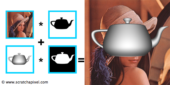
Note the on the edges of the the 3D objects, the opacity is not necessarily 1. This is due to anti-aliasing a technique we will describe later in this series of lessons. Alpha compositing can be performed using the following code:
class Rgb { ... float rgb[3]; };
class Rgba { ... float rgb[3]; float alpha; };
Rgb pixelComp;
const Rgb& pixelBG = ImageA.getPixel(x, y);
const Rgba& pixelFG = ImageB.getPixel(x, y);
pixelComp = pixelBG * (1 - pixelFG.alpha) + pixelFG * pixelFG.Alpha;
We rarely do compositing in a renderer and leave this task to a specialised 2D application (such as Photoshop for still images, Nuke for professional VFX work). Developped in the late 1970s, the concept of alpha channel was fully presented by Thomas Porter and Tom Duff (working for Lucasfilm at the time) in 1984 in a seminal paper entitled "Compositing Digital Images". More information on image digital compositing can be found in the 2D section.
A Formal Definition: Pixels are Sample not Little Squares
What are pixels exactly? Most of the times, and for the purpose of simplification it's rarely necessary to explain that a pixel is nothing more than a little square, similar to what a brick is to a wall. The world that is around us is made of objects whose surfaces are continuous. However when we take a digital photograph, we turn these continuous surfaces into a set of discrete samples whose colors represent the average color of the objects across the projected area of each pixel. This process is illustrated in the following figure:
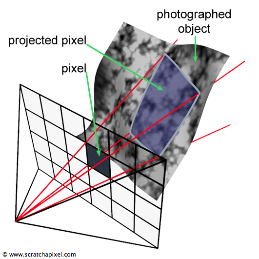
In conclusion we can say that a a pixel is a sample of the photographed object's surface. All the pixels of an images are independent from each other and they all represent samples from the scene we looked at. In mathematics, converting a continuous function to a set of samples is called discretisation. Seeing pixels that way is important because the topic of discretisation or sampling a continuous function as well as reconstructing a function from a set of discrete samples are processes for which many techniques have been developed and which are intensively used in computer graphics (check the lesson on Aliasing for instance).
Conclusion
In this chapter, we have reviewed the most important concepts regarding digital image files. An digital image is a two-dimensional array of RGB or RGBA pixels whose dimension is defined by the number of pixels along the width (number of columns) and the number of pixels along the height (number of rows) of this array. Digital images images can also be visualised (for instance in Photoshop) as three two-dimensional arrays of numbers (one for each primary color, red, green and blue) which are called channels. Images can potentially have a fourth channel (when the are computer generated), the alpha channel which represents the opacity of the objects in the 3D scene. The alpha channel is useful to compose computer generated elements on top of photographs (which are called plates in the world of visual effects) or other computer generated images (backgrounds). A file format defines how the RGB image data is saved to a file. In theory this data can be saved in any form as long as the content of the image can be read back and displayed on the screen properly. However file formats are usually designed with specific goals in mind, such as compressing the image data to make the file size as small as possible (JPG format for instance), storing the image data in floating-point precision (RAW, OpenEXR) rather than bytes (PNG), or designed to be easy to implement (PPM). If the image file uses a bit length (number of bits per pixel) which is different than the one in which the computer generated image is defined, we will need to convert the pixel values to another number representation before saving them to disk, a process which is called quantization. Finally remember than pixels are better seen as samples representing objects from the photographed scene (and that's true of real world photographs as well as computer generated images) than squares.
Source Code
In this lesson, we provide the source code of a simple program to read and write PPM files. In the lesson Simple Image Manipulations, we will learn how to add more functionalities to the image class.
Reference
Color Image Quantization for Frame Buffer Display, Paul S. Heckbert (1982).
Compositing Digital Images, Porter (1984).