Controlling CG Lighting: Exposure, Grey Zone, and Grey Balls
Reading time: 13 mins.This lesson was originally written in the early 2000s. While some aspects may be a bit outdated—given that the processes used in CGI studios have evolved considerably—I do plan to revisit this lesson in the future. However, it contains valuable information, both historical and practical, that can be useful for understanding the next lesson, "An Introduction to Lighting." Therefore, I have decided to republish it nonetheless (March 2024), prior to that planned update.
About the Albedo and the 0.18 Magic Number
The challenge in creating CG images for film is integrating these images with live-action footage. These "film" images are produced using lighting techniques developed over many years by photographers, film labs, camera manufacturers, and DPs (Director of Photography). The goal of these techniques is to develop a set of procedures to control the look of images and, especially, ensure consistency between images shot in different lighting conditions. This often involves answering the question, "What is a properly exposed image?" Properly exposed means, "How do I optimally map the dynamic range of the scene to the dynamic range of the film?" The difficulty of taking a picture that is properly exposed is that it takes into account many variables, from the sensitivity of the film to the lighting conditions and the brightness of the objects being filmed.
These techniques are based on work done in sensitometry in the late 19th century, which got formalized (early-mid 20th century) by photographer Ansel Adams in a photographic technique known as the Zone System (which is explained in a separate lesson). The principle of this technique is based on the observation that the average reflectance of diffuse objects (or albedo, as stated above) in the real world stands around the 0.18 value. Ansel Adams used this observation and related it somehow to the optical properties of the photographic film.
The average reflectance of Caucasian skin falls within the range of 0.18 to 0.25, depending on the skin's complexion. You can find a short list of albedo values for some common materials on the Wikipedia page devoted to albedo.
Photographic film, as well as CCDs (charge-coupled devices) used in digital cameras, can only record a certain range of light intensity values (the dynamic range of the film should not be confused with film sensitivity, which we won't discuss here as it introduces another variable to the problem). Ideally, a director of photography or photographer wants the main subject of their composition to be properly exposed, meaning that the values recorded on the film for this subject will ideally fall in the middle of that range (what we call mid-tones). Anything above is a highlight, and anything below is a shadow.
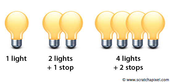
Before we delve into the technique developed by Adams, we need to introduce the concept of a stop. Generally speaking, the concept of a stop is used in photography to quantify a relative change in the intensity of light. If you have one light bulb and you add another one, we say that the light intensity has increased by a stop. If you add two more bulbs, it increases by another stop, four light bulbs by another, and so on. To double the light intensity is one stop brighter (+1 stop), and to halve the light intensity is one stop darker (-1 stop). Note how the number of bulbs needed to increase the light intensity by a stop can be expressed as a power of 2 (2 raised to the exponent n, where n is the number of stops).
Aperture, speed, and film sensitivity are all expressed in terms of stops, even though they use different numbering systems. Changing the aperture size on a lens will either increase or decrease the amount of light passing through the lens by a full stop. Photographers use this aperture setting to control exposure.
Now, let's assume that we take a properly exposed photograph of a grey card, which is made of solid grey color that reflects exactly 18% of the light it receives (18% is the value we have described before as being the average reflectance of diffuse objects in the real world). Explaining what "properly exposed" means here could take a very long time, but let's just say, in short, that every film is defined by what is called a density curve (or characteristic curve). This curve (a plot of the optical density against the light brightness, i.e., the number of photons per second or the relative exposure) indicates how the optical density of the film changes as it is exposed to various amounts of light. This curve has an "S" shape because film does not react linearly to linear changes in light brightness, similar to the eye.
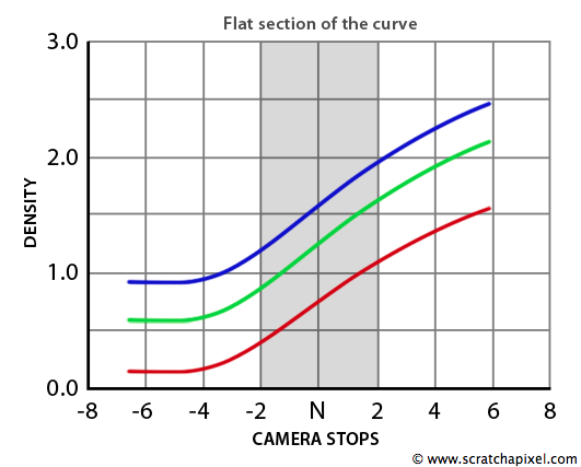
This is not much of a problem because the middle of the curve is almost linear. Without going into more detail, let's say that a scene is properly exposed when the main subject of the photograph is represented on the film by optical density values that fall in the middle of that curve (the straight part). Let's call this sweet spot (the camera settings that give a properly exposed image of the grey card) exposure 0. From there, we can take a series of pictures that are 1 stop apart. First, we will change the aperture to get 1 stop darker and take pictures until the image gets completely black. For generic photographic films (such as the Kodak 5245, which was very commonly used by DPs before the use of digital cameras), we will find that we have a latitude of about 7 stops below exposure 0 before we get to that point. We can then repeat the process, but this time we will get 1 stop brighter and take a series of pictures until the resulting image is completely white. The range of stops in that case should be, on average, about 5 stops above exposure 0. Ideally, a photographer or DP wants the main subject from the frame to fall in the middle of that range (the middle of the S-shaped curve), with about 5 to 6 stops below to capture the shadows and about 4 to 5 stops above to capture the highlights (this, in short, is what Ansel Adams' technique is about). We use a grey card to adjust the camera aperture because it usually represents an average of the objects' reflectance that are in the frame. If the film is properly exposed (that is, if the aperture on the camera was properly set), then the image of the grey card on the negative should have a density that falls in the middle of the densitometric curve.

In Adams' system, the range of the film is divided into 11 zones. Zone 5 corresponds to middle grey (18% reflectance). Zone 6 represents Caucasian skin. Zone 0 is pure black, and zone 10 is pure white. Discussion on the zone system and the use of the Macbeth chart in cinematography is discussed in a separate lesson.
The challenge with CG, as we know it, is that all the values we use to create an image are relative. We could render two identical images by either decreasing the brightness of an object and increasing the light or increasing the brightness of the object and decreasing the light. There are two issues at this point. In theory, there's an infinity of combinations that could produce the same CG pictures as we mentioned before by just changing the ratio between the object's brightness and the light intensity. However, having very dark objects and very bright lights is probably not the way to go. The second problem is that it is potentially hard to appreciate the change you need to make to your lighting or your camera settings when someone asks you to "make an image brighter or darker." Talking about an image is very subjective, and DPs speak about image brightness and lighting in terms of stops instead of more subjective terms such as darker and brighter (because a stop is a measurable and controllable value that everyone working on a film set or in a film lab can relate to in a similar way).
Making that bridge between real-world photography and CG was initiated by a group of people who developed a CG pipeline at ILM in the early '80s. Some of these people had a background in traditional film processing and were therefore very familiar with the concepts used in real photography and film, such as optical density, object reflectivity, and stop. Their idea was to say that the diffuse color of a CG object should be the same as a real-world object's reflectivity. In other words, the grey card should be represented in CG by a diffuse color of 0.18. Now remember that the relative exposure for a film properly exposed is 0, and that a DP can decide to make the picture brighter or darker by a certain measurable stop value by either adding more light to the scene (which they can measure with a light meter) or changing the camera settings. All indications regarding how much darker or brighter the image should be will be defined in terms of stop under or stop over that relative 0 exposure. The idea in CG is to achieve the same effect by setting the numerical value 0.18 as having a relative exposure of 0. Since stops obey a power of 2, the brightness of a pixel expressed in "stop" can be computed using the inverse of the power 2, which is a log in base 2. Since \(\log_2(1) = 0\), to get a 0 exposure from a 0.18 value, we need to use the following equation:
$$ \log_2\left(\frac{\text{pixel brightness}}{0.18}\right) = \text{pixel exposure} $$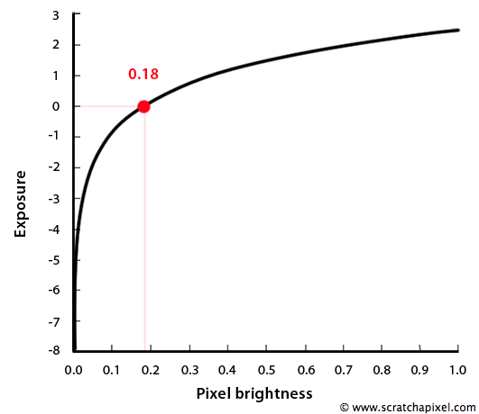
The concepts we have described are behind the idea of setting the diffuse default color for CG objects to 0.18 and measuring the pixel brightness from a CG frame in terms of stops. Ideally, the RGB values of the light color shouldn't be higher than 1 so that you can easily adjust its hue and saturation in a color picker. To adjust the overall intensity of the light, you might want to use an exposure control instead (if it's available to you). The final value for the light is computed as the light color multiplied by \(2^\text{light exposure}\).
Let's imagine that the diffuse default color is 0.18 and that you illuminate an object with a dome light whose intensity is 1 (light color is 1 and light exposure is 0). We have learned in the first chapter that the object brightness should then be 0.18. If you want to increase the object brightness by 1 stop, you will set the light exposure to 1, which corresponds to an overall light intensity (\(Li\)) of 2 (\(Li = 1 \times 2^1 = 2\)). The object brightness is now 0.36. If you want to increase the light by 2 stops, you set the light exposure to 2, and the final light intensity will be 4 (\(Li = 1 \times 2^2 = 4\)). The object brightness is now 0.72. We increased the exposure by 2 stops, but we have 4 times more light than with exposure 0. Note that this also works for negative light exposure values (1 stop darker means \(Li = 1 \times 2^{-1} = 0.5\), 2 stops darker \(Li = 1 \times 2^{-2} = 0.25\)).
Matching the Grey Ball
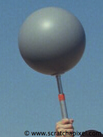
If you've worked in a studio producing CGI for films, you're probably familiar with the use of grey balls. They are used on set as lighting references. As its name suggests, the ball is covered with the same paint used to make grey cards. In other words, its reflectance is also 18%. Ideally, the grey ball should be a perfect diffuse object, but this is usually not the case. Those used on set are often slightly shiny (image on the left), but it's not intentional (not much effort is put into making them really matte). We know that the camera aperture on set has been set so that middle grey (18% reflectance) falls in the middle of the range of brightness values that the photographic film or the digital sensor (for digital cameras) can capture. If the camera was properly set, then we can use the grey ball as a lighting reference. The ball, of course, is not flat like the grey card and captures light information coming from all directions (spherical). In post-production, we will adjust the lighting (create new lights, move existing ones, adjust their colors and exposures, etc.) until the render of a CG grey ball (a sphere to which a diffuse material whose diffuse color is set to 0.18 is attached) matches the live-action grey ball. Once the lighting matches the lighting from the plate (which is the case if the CG and live-action grey balls look the same), in theory, 3D models rendered with this lighting setup should match very closely the lighting of objects or characters from the live-action plate. One more note: In post-production, plates are usually scanned if the film wasn't shot with a digital camera (which is becoming the norm nowadays). This plate is brought up in the same viewing program used to display CG renders. Usually, these programs can measure pixel brightness values in terms of stops. To adjust the lighting of a 3D scene, we will measure the exposure of the grey balls in several places (usually the key and shadow area), then compare these values to the values we read in the same places on the CG grey ball. We can adjust the lighting until these values match. Working in terms of stops makes it much easier to adjust light intensities. For instance, if we find on the key side of the CG grey ball that the exposure is 1 stop darker than on the key side of the live-action grey ball, then all we need to do is increase the key light from the scene by 1 stop to get them to match.
Using grey balls as lighting reference and creating HDR light probe images to match the lighting of real photographs is explained in a separate lesson.