File Formats to Store Polygon Meshes: OBJ, FBX, RenderMan, glTF, USD, etc.
Reading time: 17 mins.Storing Polygon Meshes
When it comes to rendering, you can always define the mesh directly in the source code of the program but this is limited. If you need to recompile the program every time you want to render an image of a new model, it would be impractical. For the sake of completeness, we will still study the option in this chapter. Generally, the model data is never stored in the program's code but is stored in a separate file instead. Most 3D rendering programs expect a scene file as input, read the content of that file which contains information about the camera, the lights, and the geometry contained in the scene, and pass this information to the engine that finally renders an image of that scene. In this chapter we will look at how polygon meshes are stored in three of the most common file formats: RIB (RenderMan), OBJ, and FBX. Finally, we will write our format to facilitate the import of geometry into our programs.
In C++
As mentioned above, it is possible to define the mesh data directly in the program's source code, though this is not only impractical but also to be avoided in general. It slows down the compilation process and can increase the program file to a large extent (the executable file). It can however be convenient when you write a prototype and don't want to deal with the complications that invariably come with implementing a scene file importer.
We already studied this code in the previous chapter. All you need to do is declare a face index array, whose size needs to be known in advance (lines 1 and 2). You also need a vertex index array (line 3) and of course the vertex array itself (the position of the vertices in 3D space - line 4). Note that the size of these two arrays can be computed directly from the face index array. The size of the vertex index array can be computed by summing up each element of the face index array (6 times 4 in the case of the cube - line 9). The size of the vertex array can be computed by finding out the maximum value in the face index array plus 1 (don't forget that all arrays in C++ are 0-based - line 15).
uint32_t numFaces = 6;
int faceIndex[numFaces] = {4, 4, 4, 4, 4, 4};
int vertexIndex[24] = {0, 1, 2, 3, 0, 4, 5, 1, 1, 5, 6, 2, 0, 3, 7, 4, 5, 4, 7, 6, 2, 6, 7, 3};
Vec3f verts[8] = {{-1,1,1},{1,1,1},{1,1,-1},{-1,1,-1},{-1,-1,1},{1,-1,1},{1,-1,-1},{-1,-1,-1}};
Vec2f uvs[24] = {{0.375, 0},{0.625, 0} ... {0.125, 0.25}};
// first compute how many vertices we expect
uint32_t numVertices = 0;
for (int i = 0; i < numFaces; ++i) {
    numVertices += faceIndex[i];
}

// find max size of the vertex array
uint32_t maxVertexIndex = 0;
for (int i = 0; i < numVertices; ++i) {
    if (maxVertexIndex < vertexIndex[i]) maxVertexIndex = vertexIndex[i];
}
maxVertexIndex += 1;

// loop other all faces
int offset = 0;
for (int i = 0; i < numFaces; ++i) {
    std::cerr << "Face: " << i << " has " << faceIndex[i] << " vertices\n";
    for (int j = 0; j < faceIndex[i]; ++j) {
         int vertIndex = vertexIndex[offset + j];
         std::cerr << j << " vertex index: " << vertIndex << " pos: " << verts[verIndex] << "\n";
    }
    offset += faceIndex[i];
}
RIB (RenderMan)
RIB stands for RenderMan Interface Bytestream (RIB files have the extension .rib). It is the format used by Pixar to pass scene data to their renderer (the renderer currently used in production is called RIS. It was preceded by Prman with which many famous Pixar films were produced: Toy Story, Finding Nemo, Monsters Inc., Wall-E, etc. RIB files can either be stored in binary or ASCII. Here is what our cube looks like in a RIB file:
PointsPolygons [4 4 4 4 4 4] [0 1 3 2 2 3 5 4 4 5 7 6 6 7 1 0 1 7 5 3 6 0 2 4] "P" [-0.5 -0.5 0.5 0.5 -0.5 0.5 -0.5 0.5 0.5 0.5 0.5 0.5 -0.5 0.5 -0.5 0.5 0.5 -0.5 -0.5 -0.5 -0.5 0.5 -0.5 -0.5] "facevarying normal N" [0 0 1 0 0 1 0 0 1 0 0 1 0 1 0 0 1 0 0 1 0 0 1 0 0 0 -1 0 0 -1 0 0 -1 0 0 -1 0 -1 0 0 -1 0 0 -1 0 0 -1 0 1 0 0 1 0 0 1 0 0 1 0 0 -1 0 0 -1 0 0 -1 0 0 -1 0 0] "facevarying float s" [0.375 0.625 0.625 0.375 0.375 0.625 0.625 0.375 0.375 0.625 0.625 0.375 0.375 0.625 0.625 0.375 0.625 0.875 0.875 0.625 0.125 0.375 0.375 0.125] "facevarying float t" [0 0 0.25 0.25 0.25 0.25 0.5 0.5 0.5 0.5 0.75 0.75 0.75 0.75 1 1 0 0 0.25 0.25 0 0 0.25 0.25] "constant string primtype" ["mesh"]
We already talked about this format in the previous chapter. The declaration starts with the request PointsPolygons. The first array is the face index array. It is followed by the vertex index array. Each following array defines a primitive variable. The first one "P" is mandatory (it contains the position of the mesh vertices). All others (in this example N and st) are optional.
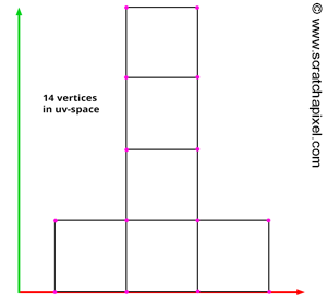
Note that in this format, the normal and texture coordinates array have the size of the vertex index array. The number of normals and texture coordinates in the array is equal to the sum of all the face's number of vertices. For a cube, this number is 24 (there are 6 faces in a cube and each face has 4 vertices). For texture coordinates though, you can see by looking at figure 1, then only 14 coordinates are needed (it depends on the way you layout the cube's uvs though. You could as well split the faces in uv space in which case you need 24 texture coordinates). Declaring 24 textures coordinates instead of only 14 is not optimum though declaring the uv coordinates for each vertex of each face of the mesh saves us from having to use a texture coordinates index array. Check the OBJ or FBX file formats to see an example of a texture or normal index array.
OBJ Format
The OBJ file format is a pretty old but common file format originally developed by Wavefront (OBJ files have the extension .obj). To the difference of the RIB interface or other formats such as FBX, OBJ only stores geometry data (and no other scene data such as lights or cameras). Many different geometry types and geometry data can be stored in this format (such as information about the material of the object) though, in the context of this lesson, we will only study how polygon meshes are defined in an OBJ file. Here is what our cube looks like in this format:
# This file uses centimeters as units for non-parametric coordinates.

v -0.500000 -0.500000 0.500000
v 0.500000 -0.500000 0.500000
v -0.500000 0.500000 0.500000
v 0.500000 0.500000 0.500000
v -0.500000 0.500000 -0.500000
v 0.500000 0.500000 -0.500000
v -0.500000 -0.500000 -0.500000
v 0.500000 -0.500000 -0.500000
vt 0.375000 0.000000
vt 0.625000 0.000000
vt 0.375000 0.250000
vt 0.625000 0.250000
vt 0.375000 0.500000
vt 0.625000 0.500000
vt 0.375000 0.750000
vt 0.625000 0.750000
vt 0.375000 1.000000
vt 0.625000 1.000000
vt 0.875000 0.000000
vt 0.875000 0.250000
vt 0.125000 0.000000
vt 0.125000 0.250000
vn 0.000000 0.000000 1.000000
vn 0.000000 0.000000 1.000000
vn 0.000000 0.000000 1.000000
vn 0.000000 0.000000 1.000000
vn 0.000000 1.000000 0.000000
vn 0.000000 1.000000 0.000000
vn 0.000000 1.000000 0.000000
vn 0.000000 1.000000 0.000000
vn 0.000000 0.000000 -1.000000
vn 0.000000 0.000000 -1.000000
vn 0.000000 0.000000 -1.000000
vn 0.000000 0.000000 -1.000000
vn 0.000000 -1.000000 0.000000
vn 0.000000 -1.000000 0.000000
vn 0.000000 -1.000000 0.000000
vn 0.000000 -1.000000 0.000000
vn 1.000000 0.000000 0.000000
vn 1.000000 0.000000 0.000000
vn 1.000000 0.000000 0.000000
vn 1.000000 0.000000 0.000000
vn -1.000000 0.000000 0.000000
vn -1.000000 0.000000 0.000000
vn -1.000000 0.000000 0.000000
vn -1.000000 0.000000 0.000000
f 1/1/1 2/2/2 4/4/3 3/3/4
f 3/3/5 4/4/6 6/6/7 5/5/8
f 5/5/9 6/6/10 8/8/11 7/7/12
f 7/7/13 8/8/14 2/10/15 1/9/16
f 2/2/17 8/11/18 6/12/19 4/4/20
f 7/13/21 1/1/22 3/3/23 5/14/24
Each line in the file starts with a letter that represents the type of data the following numbers represent. If the line starts with the letter v then the next 3 following numbers declare the position of a vertex. The index of the vertex in the mesh is defined by its position in the file. If the line starts with the letters vt, then the next 2 following numbers define texture coordinates. The letters vn means that the next 3 following numbers define a normal. Finally, the letter f defines a face declaration. It is followed by at least 3 groups of three numbers separated by a '/'. The first number defines the index of the vertex in the vertex array (the v's). The second number defines the index of the vertex texture coordinates in the texture coordinates array (the vt's). The third number defines the index of the vertex normal in the normal array (the vn's). In the OBJ file format, arrays are 1-based (the first element in the array has index 1). In the example above, the first face of the cube is defined by the first, second, fourth, and third vertices in the vertex array (1/1/1 2/2/2 4/4/3 3/3/4). The face has 4 vertices. The first vertex of that face uses the first texture coordinates in the texture coordinates array, the second vertex uses the second texture coordinates in the array, the third vertex uses the fourth texture coordinates, etc. (1/1/1 2/2/2 4/4/3 3/3/4). Similarly, for the normals, the first vertex uses the first normal in the normal array, the second vertex uses the second normal, the third vertex the third normal, etc. (1/1/1 2/2/2 4/4/3 3/3/4)
Note that in this format (as well as in the FBX format), the index of the vertices in the texture coordinates array is part of the face definition. Only 14 texture coordinates are exported to the OBJ file, but for each vertex of the cube, we now need to define the index of the vertex in this array. The same thing applies to normals.
FBX
FBX is an Autodesk proprietary file format (FBX files have the extension .fbx). It is used to facilitate the transfer of scene data between applications developed by Autodesk (such as Maya and 3DSMax). It is not an open file format and the specifications of the format don't officially exist, though the content of an FBX file can be looked at if stored in ASCII. The FBX file format is quite popular as an interchanged file format between 3D applications and can describe most elements making up a scene (geometry, lights, materials, camera, material assignments, layers, etc.). Here is what our cube looks like in FBX:
; FBX 7.4.0 project file
; Copyright (C) 1997-2010 Autodesk Inc. and/or its licensors.
; All rights reserved.
; ----------------------------------------------------

Objects:  {
    Geometry: 140208557167936, "Geometry::", "Mesh" {
        Vertices: *24 {
               a: -0.5,-0.5,0.5,0.5,-0.5,0.5,-0.5,0.5,0.5,0.5,0.5,0.5,-0.5,0.5,-0.5,0.5,0.5,-0.5,-0.5,-0.5,-0.5,0.5,-0.5,-0.5
        }
        PolygonVertexIndex: *24 {
            a: 0,1,3,-3,2,3,5,-5,4,5,7,-7,6,7,1,-1,1,7,5,-4,6,0,2,-5
        }
        Edges: *12 {
            a: 0,2,6,10,3,1,7,5,11,9,15,13
        }
        GeometryVersion: 124
        LayerElementNormal: 0 {
            Normals: *72 {
                a: 0,0,1,0,0,1,0,0,1,0,0,1,0,1,0,0,1,0,0,1,0,0,1,0,0,0,-1,0,0,-1,0,0,-1,0,0,-1,0,-1,0,0,-1,0,0,-1,0,0,-1,0,1,0,0,1,0,0,1,0,0,1,0,0,-1,0,0,-1,0,0,-1,0,0,-1,0,0
            }
            NormalsW: *24 {
                a: 1,1,1,1,1,1,1,1,1,1,1,1,1,1,1,1,1,1,1,1,1,1,1,1
            }
        }
        LayerElementUV: 0 {
            UV: *28 {
                a: 0.375,0,0.625,0,0.375,0.25,0.625,0.25,0.375,0.5,0.625,0.5,0.375,0.75,0.625,0.75,0.375,1,0.625,1,0.875,0,0.875,0.25,0.125,0,0.125,0.25
            }
            UVIndex: *24 {
                a: 0,1,3,2,2,3,5,4,4,5,7,6,6,7,9,8,1,10,11,3,12,0,2,13
            }
        }
    }
}
In the FBX format, the face index and vertex index arrays are combined in one single array. If you look at the array called PolygonVertexIndex in the example above, you will notice that it contains some negative values. These negative values are used to indicate the end of a face. For example in the example above, the first face has 4 vertices (0, 1, 3, -3). To find the index of the fourth vertex, you simply multiply the index value by -1 and remove 1 from the result. For example:
-3 * - 1 - 1 = 2
Thus, the first face is composed of the vertices with indexes 0, 1, 3, and 2 in the vertex array. The second face has also 4 vertices. Their indices in the vertex array are 2, 3, 5, and 4 (-5 * -1 - 1 = 4), and so on. You need to parse the entire PolygonVertexIndex array to know how many faces the mesh contains.
What About Other Formats such as USD and glTF?
The glTF format is particularly common in the video game industry. It's a lightweight format whose specifications are developed and maintained by the Khronos Group. We won't be dwelling on it now too much but will write a lesson about it in the future. Like FBX it's a rather polyvalent/versatile format that supports geometry, texture, camera, and light storage/definition. It comes in ASCII and binary forms.
Other more recent formats are emerging such as USD. USD stands for Universal Scene Description (an ambitious goal). The format was initially developed by Pixar to fit its internal production needs (before 2013). USD is not a format in the sense that it comes with specifications that you can follow to read and write USD-compatible files. When we speak about USD we rather refer to the code that Pixar released as an open-source project in 2016. The code provides the framework as well as some auxiliary tools that allows you to read and write USD file as well as expose the data stored in USD format to renderers (through an interface called Hydra). The USD code base is rather daunting and USD is also a rather complex format. Its main goal is to ease the aggregation of data coming from various sources and combine them into scene data through a mechanism called composition. It supports many features such as layering, parameter overrides, class inheritance, variations, payloads, and much more. It's a rather complicated and overwhelming format that we will write about in a future lesson. In the meantime, if you are interested to start reading more about the format you go the Pixar's website.
Our Format?
Many of the programs we write on Scratchapixel require a polygon mesh. Thus somehow we need to find a way of loading that mesh in our program. The problem with many of the file formats we have mentioned in this chapter is that they are not that easy to parse (especially the FBX file format) plus our goal isn't to teach how to write a scene file parser (though we plan on writing a lesson on this topic in the future).
What can we do? We can write our file format. The reason to do so is essential to expose the data that we need in a way that is simple to read. This will keep the code needed to read that data as small as possible. We will simply serialize the data making up the mesh into an ASCII file. The file looks like that:
6 4 4 4 4 4 4 0 1 2 3 0 4 5 1 1 5 6 2 0 3 7 4 5 4 7 6 2 6 7 3 -1 1 1 1 1 1 1 1 -1 -1 1 -1 -1 -1 1 1 -1 1 1 -1 -1 -1 -1 -1 0 0 1 0 0 1 0 0 1 0 0 1 0 1 0 0 1 0 0 1 0 0 1 0 0 0 -1 0 0 -1 0 0 -1 0 0 -1 0 -1 0 0 -1 0 0 -1 0 0 -1 0 1 0 0 1 0 0 1 0 0 1 0 0 -1 0 0 -1 0 0 -1 0 0 -1 0 0 0.375 0.625 0.625 0.375 0.375 0.625 0.625 0.375 0.375 0.625 0.625 0.375 0.375 0.625 0.625 0.375 0.625 0.875 0.875 0.625 0.125 0.375 0.375 0.125 0.375 0.625 0.625 0.375 0.375 0.625 0.625 0.375 0.375 0.625 0.625 0.375 0.375 0.625 0.625 0.375 0.625 0.875 0.875 0.625 0.125 0.375 0.375 0.125
The first number defines the number of faces making up the mesh. The second and third line is just a series of integers representing the face index and the vertex index arrays. The next line contains the vertex position data. The next line contains the normal data and finally, the last line contains the texture coordinates data. This format has the advantage of being simple to read with a computer. To do so, we will use the following code:
void loadGeoFile(const char *file)
{
    std::ifstream ifs;
    try {
        ifs.open(file);
        if (ifs.fail()) throw;
        std::stringstream ss;
        ss << ifs.rdbuf();
        uint32_t numFaces;
        ss >> numFaces;
        std::cerr << "Mesh has " << numFaces << " faces " << std::endl;
        std::unique_ptr<uint32_t []> faceIndex(new uint32_t[numFaces]);
        uint32_t vertsIndexArraySize = 0;
        // reading face index array
        for (uint32_t i = 0; i < numFaces; ++i) {
            ss >> faceIndex[i];
            vertsIndexArraySize += faceIndex[i];
            std::cerr << faceIndex[i] << std::endl;
        }
        std::cerr << "Verts index array size " << vertsIndexArraySize << std::endl;
        std::unique_ptr<uint32_t []> vertsIndex(new uint32_t[vertsIndexArraySize]);
        uint32_t vertsArraySize = 0;
        // reading vertex index array
        for (uint32_t i = 0; i < vertsIndexArraySize; ++i) {
            ss >> vertsIndex[i];
            if (vertsIndex[i] > vertsArraySize) vertsArraySize = vertsIndex[i];
            std::cerr << vertsIndex[i] << std::endl;
        }
        vertsArraySize += 1;
        std::cerr << "Max verts index " << vertsArraySize << std::endl;
        // reading vertices
        std::unique_ptr<Vec3f []> verts(new Vec3f[vertsArraySize]);
        for (uint32_t i = 0; i < vertsArraySize; ++i) {
            ss >> verts[i].x >> verts[i].y >> verts[i].z;
            std::cerr << verts[i] << std::endl;
        }
        // reading normals
        std::cerr << "Reading normals\n";
        std::unique_ptr<Vec3f []> normals(new Vec3f[vertsIndexArraySize]);
        for (uint32_t i = 0; i < vertsIndexArraySize; ++i) {
            ss >> normals[i].x >> normals[i].y >> normals[i].z;
            std::cerr << normals[i] << std::endl;
        }
        // reading st coordinates
        std::cerr << "Reading texture coordinates\n";
        std::unique_ptr<Vec2f []> st(new Vec2f[vertsIndexArraySize]);
        for (uint32_t i = 0; i < vertsIndexArraySize; ++i) {
            ss >> st[i].x >> st[i].y;
            std::cerr << st[i] << std::endl;
        }

        createMesh(numFaces, faceIndex, vertsIndexArraySize, vertsIndex, vertsArraySize, verts, normals, st);
    }
    catch (...) {
        ifs.close();
    }
    ifs.close();
}
This approach also has its disadvantages. For instance, we read the entire file in memory (line 8) before parsing it. If the file is large, this might take a lot of memory before we even manage to transfer the content of the file to the engine. Ideally, you might only need to read individual chunks if and when you need them. Though, we don't intend to read large geometry files for our simple programs anyway so that should never in practice be a problem.
We added this function to the code of the CPU rasterizer which we developed for the lesson Rasterization: a Practical Implementation. In the lesson on rasterization, we chose to define the geometry data directly in the code, which as explained earlier is not the ideal solution. In this lesson, we read the geometry data from an external file using a modified version of the code above (the geometry is triangulated thus we can skip the face index array and the normal vertex array which we don't use). Check the file raster3d.cpp in the source code section at the end of the lesson.
We plan to write a lesson on parsing scene data files in the future. Until then though, we will use this code and this simple geometry file format to load meshes in our programs.