Generating Camera Rays
Reading time: 22 mins.Generating Camera Rays
First, let's recall that the purpose of a renderer is to assign a color to each pixel of the frame. The result must be an accurate representation of the scene geometry as seen from a particular 3D viewpoint. We also know from the previous chapter that parameters such as the field of view change how much of the scene we see. We have also explained in lesson 1 and in this lesson, that ray-traced images are created by generating one ray for each pixel in the frame. When a ray intersects an object from the scene, we set the pixel's color with the object's color at the intersection point. This process which we have already talked about in lesson 1 but will detail again in the next lessons, is known as backward or eye-tracing (because we follow the path of light rays from the camera to the object and from the object to the source, rather than from the light source to the object, and from the object to the camera).
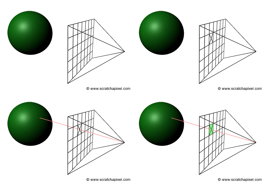
Naturally, the process of creating an image will start with constructing these rays which we call primary or camera rays (primary because these are the first rays we will cast into the scene. Secondary rays are shadows rays for example which we will talk about later). What do we know about these rays that would help us to construct them? We know that they start from the camera's origin. In almost all 3D applications, the default position of a camera when it is created is the origin of the world, which is defined by the point with coordinates (0, 0, 0). Remember from the lesson 3D Viewing: the Pinhole Camera Model, that the origin of the camera can be seen as the aperture of a pinhole camera (which is also the center of projection). The film of real-world pinhole cameras is located behind the aperture, which causes the light rays by geometrical construction to form an inverted image of the scene. However, this inversion can be avoided if the film plane lies on the same side as the scene (in front of the aperture rather than behind). By convention, in ray tracing, it is often placed exactly 1 unit away from the camera's origin (this distance will never change and we will explain why further down). By convention, we will also orient the camera along the negative z-axis (the camera default orientation is left to the developer's choice, however generally the camera is oriented along either the positive or the negative z-axis. RenderMan, Maya, PBRT, and OpenGL align the camera along the negative z-axis and we suggest developers to follow the same convention). Finally, to make the beginning of the demonstration simpler, we will assume that our rendered image is square (the width and the height of the image in pixels are the same).
Our task consists of creating a primary ray for each pixel of the frame. This can easily be done by tracing a line starting at the camera's origin and passing through the middle of each pixel (figure 1). We can express this line in the form of a ray whose origin is the camera's origin and whose direction is the vector from the camera's origin to the pixel center. To compute the position of a point at the center of a pixel, we need to convert the pixel coordinates which are originally expressed in raster space (the point coordinates are expressed in pixels with the coordinates (0,0) being the top-left corner of the frame) to world space.
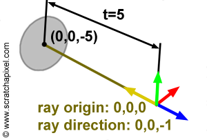
Why world space? World space is the space in which all objects of the scene, the geometry, the lights, and the cameras have their coordinates expressed into. For example, if a disk is located 5 units away from the world origin along the negative z-axis the world space coordinates of the disk are (0, 0, -5). If we want the mathematics for computing the intersection of a ray with this disk to work, the ray's origin and direction too, need to be defined in the same space. For example, if a ray has origin (0, 0, 0) and direction (0, 0, -1) where these numbers represent coordinates in the world space coordinate system, then the ray will intersect the disk at (0, 0, -5). This is shown in figure 3.
You can find more information on spaces in the lesson Computing the Pixel Coordinates of a 3D point.
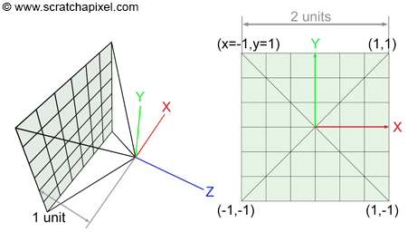
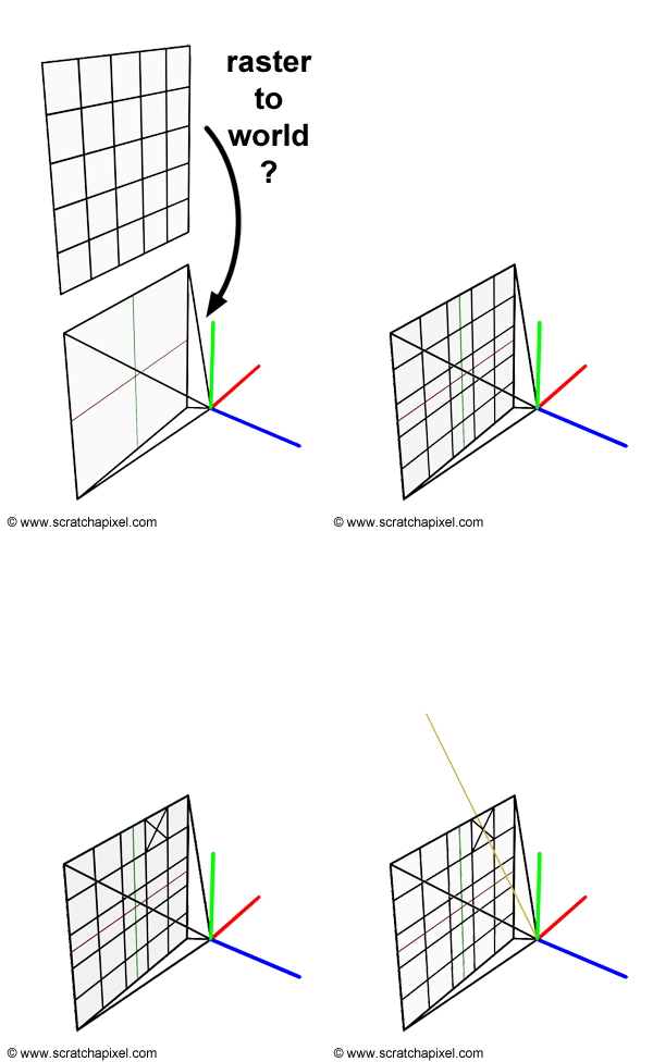
Another way of looking at the problem we are trying to solve is to start from the camera. We know the image plane is located exactly one unit away from the world origin and aligned along the negative z-axis. We also know that the image is square therefore the portion of the image plane on which the image is projected is also necessarily square. For reasons we will be explaining soon, the dimension of this projection area is 2 by 2 units (figure 2). We also know that a raster image is made of pixels. What we need is to find a relation between the coordinates of these pixels in raster space and the coordinates of the same pixels but expressed in world space. This process requires a few steps which are shown in figure 5.

We first need to normalize this pixel position using the frame's dimensions. The new normalized coordinates of the pixels are said to be defined in NDC space (which stands for Normalized Device Coordinates):
$$ \begin{array}{l} PixelNDC_x = \dfrac{(Pixel_x + 0.5)}{ImageWidth},\\ PixelNDC_y = \dfrac{(Pixel_y + 0.5)}{ImageHeight}. \end{array} $$Note that we add a small shift (0.5) to the pixel position because we want the final camera ray to pass through the middle of the pixel. Pixel coordinates expressed in NDC space are in the range [0,1] (yes, NDC space in ray tracing is different than NDC space in the rasterization world where it generally maps to the range [-1,1]). As you can see though in figure 2, the film or image plane is centered around the world's origin. In other words, pixels located on the left of the image should have negative x-coordinates, while those located on the right should have positive x-coordinates. The same logic applies to the y-axis. Pixels located above the line defined by the x-axis should have positive y-coordinates, while those located below should have negative y-coordinates. We can correct for this by remapping our normalized pixel coordinates which are currently in the range [0:1] to the range [-1:1]:
$$ \begin{array}{l} PixelScreen_x = 2 * {PixelNDC_x} - 1,\\ PixelScreen_y = 2 * {PixelNDC_y} - 1. \end{array} $$However notice that with this equation, \({Pixel \; Remapped_y}\) is negative for pixels located above the x-axis and positive for pixels located below (while it should be the other way around). The following formula will correct this problem:
$$ PixelScreen_y = 1 - 2 * {PixelNDC_y}.$$The value now varies from 1 to -1 as \({Pixel_y}\) varies from 0 to \({ImageWidth}\). Coordinates expressed in this manner are said to be defined in screen space.
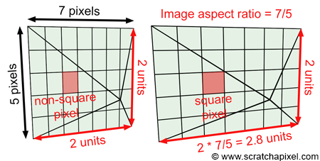
Until now though we have assumed that the image was square. Accounting for the image aspect ratio is quite simple. Let's now look at a case where the image has dimensions 7 by 5 pixels (it is a small image but an image nonetheless). Dividing the width by the height of the image gives the value 1.4\. When the pixel coordinates are defined in screen space they are in the range [-1, 1]. However, there are more pixels along the x-axis (7) than there are along the y-axis (5) therefore the pixels are squashed and elongated along the vertical axis (see figure 6). To make them square again (as pixels should be) we need to multiply the pixels' x-coordinates by the image aspect ratio, which in this case, is 1.4 (see again figure 6). Note that this operation leaves the y- pixel coordinates (in screen space) unchanged. They are still in the range [-1,1] but the x pixel coordinates are now in the range [-1.4, 1.4] (are more generally [-aspect ratio, aspect ratio]).
$$ \begin{array}{l} ImageAspectRatio = \dfrac{ImageWidth}{ImageHeight},\\ PixelCamera_x = (2 * {PixelScreen_x} - 1) * {ImageAspectRatio},\\ PixelCamera_y = (1 - 2 * {PixelScreen_y}). \end{array} $$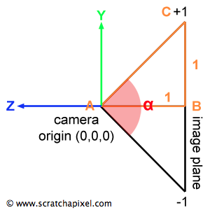
Finally, we need to account for the field of view. Note that so far, the y coordinates of any point defined in screen space are in the range [-1, 1]. We also know that the image plane is 1 unit away from the camera's origin. If we look at the camera setup from the side view, we can draw a triangle by joining the camera's origin to the top and bottom edges of the film plane. Because we know the distance from the camera's origin to the film plane (1 unit) and the height of the film plane (2 units since it goes from y=1 to y=-1) we can use some simple trigonometry to find the angle of the right triangle ABC which is half of the vertical angle \(\alpha\) (alpha), the angle we are interested in:
$${\alpha \over 2} = atan (\dfrac{OppositeSide}{AdjacentSide }) = atan(\dfrac{1}{1}) = \dfrac{\pi}{4}.$$In other words, the field of view or the angle \(\alpha\) in the particular case is 90 degrees. Now notice that to compute the length of the line BC all we need is to compute the tangent of the angle \(\alpha\) divided by 2:
$$\||BC|| = tan(\dfrac{\alpha}{2}).$$Remember from the lesson on geometry that the notation ||V|| means the length of the vector V. We can also observe that for values of \(\alpha\) greater than 90 degrees, ||BC|| is greater than 1, and for values lower than 90 degrees, ||BC|| is lower than 1\. For example if \(\alpha\)=60, tan(60/2)=0.57 and if \(\alpha\)=110, tan(110/2)=1.43\. We can therefore multiply the screen pixel coordinates (which at the moment are contained in the range [-1, 1]) by this number to scale them up or down. As you may have guessed, this operation changes how much of the scene we see, and is equivalent to zooming in (we see less of the scene when the field of view decreases) and out (and seeing more of the scene when the value of the field of view increases). In conclusion, we can define the field of view of the camera in terms of the angle \(\alpha\), and multiply the screen pixel coordinates with the result of the tangent of this angle divided by two (if this angle is expressed in degrees don't forget to convert it to radians):
$$ \begin{array}{l} PixelCamera_x = (2 * {PixelScreen_x } - 1) * ImageAspectRatio * tan(\dfrac{\alpha}{2}),\\ PixelCamera_y = (1 - 2 * {PixelScreen_y }) * tan(\dfrac{\alpha}{2}). \end{array} $$At this point, the original pixel coordinates are expressed with regard to the camera's image plane. They have been normalized, remapped between [-1:1], multiplied by the image aspect ratio, and multiplied by the tangent of the field of view angle \( \alpha\) divided by 2\. This point is said to be in camera space because its coordinates are expressed with regard to the camera's coordinate system. When the camera is in its default position, the camera's coordinate system and the world's coordinate system are aligned. The point lies on the image plane which is 1 unit away from the camera's origin but remembers that the camera is also aligned along the negative z-axis. Therefore we can express the final coordinate of the pixel on the image plane as:
$$ P_{cameraSpace} = (PixelCamera_x, PixelCamera_y, -1)$$This gives us the position P (\( P_{cameraSpace}\)) of a pixel in the image on the image plane of the camera. From there, we can compute a ray for this pixel by defining the origin of the ray as the camera's origin (let's call this point O) and the direction of the ray as the normalized vector OP (figure 8). The vector OP is simply the position of the point on the image plane minus the camera origin. The camera origin and the world Cartesian coordinate system are the same when the camera is in its default position, therefore the point O is simply (0, 0, 0).
In pseudo-code we get (you will find the actual C++ implementation at the end of the lesson):
float imageAspectRatio = imageWidth / (float)imageHeight; // assuming width > height
float Px = (2 * ((x + 0.5) / imageWidth) - 1) * tan(fov / 2 * M_PI / 180) * imageAspectRatio;
float Py = (1 - 2 * ((y + 0.5) / imageHeight) * tan(fov / 2 * M_PI / 180);
Vec3f rayOrigin(0);
Vec3f rayDirection = Vec3f(Px, Py, -1) - rayOrigin; // note that this just equal to Vec3f(Px, Py, -1);
rayDirection = normalize(rayDirection); // it's a direction so don't forget to normalize
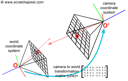
Finally, we want to be able to render an image of the scene from any particular point of view. After you have moved the camera from its original position (centered at the origin of the world coordinate system and aligned along the negative z-axis) you can express the translation and rotation values of the camera with a 4x4 matrix. Usually, this matrix is called the camera-to-world matrix (and its inverse is called the world-to-camera matrix). If we apply this camera-to-world matrix to our points O and P then the vector ||O'P'|| (where O' is the point O and P' is the point P transformed by the camera-to-world matrix) represents the normalized direction of the ray in world space (figure 8). Applying the camera-to-world transform to O and P transforms these two points from camera space to world space. Another option is to compute the ray direction while the camera is in its default position (the vector OP), and apply the camera-to-world matrix to this vector.
Note how the camera coordinate system moves with the camera. Our pseudo code can easily be modified to account for camera transformation (rotation and translation, scaling a camera are not particularly recommended):
float imageAspectRatio = imageWidth / imageHeight; // assuming width > height
float Px = (2 * ((x + 0.5) / imageWidth) - 1) * tan(fov / 2 * M_PI / 180) * imageAspectRatio;
float Py = (1 - 2 * ((y + 0.5) / imageHeight) * tan(fov / 2 * M_PI / 180);
Vec3f rayOrigin = Point3(0, 0, 0);
Matrix44f cameraToWorld;
cameraToWorld.set(...); // set matrix
Vec3f rayOriginWorld, rayPWorld;
cameraToWorld.multVectMatrix(rayOrigin, rayOriginWorld);
cameraToWorld.multVectMatrix(Vec3f(Px, Py, -1), rayPWorld);
Vec3f rayDirection = rayPWorld - rayOriginWorld;
rayDirection.normalize(); // it's a direction so don't forget to normalize
To compute the final image we will need to create a ray for each pixel of the frame using the method we have just described and test if any one of these rays intersects the geometry from the scene. Unfortunately, we are not to a point yet in this series of lessons where we can compute the intersection between rays and objects but this will be the topic of the next two lessons.
Source Code
The source code of this lesson is just a simple example of how the rays can be generated for each pixel of an image. The code loops over all the pixels of the image (line 13-14), and compute a ray for the current pixel. We have combined all the remapping steps described in this chapter in one single line of code. The original x-pixel coordinate is divided by the image width to remap the initial coordinate to the range [0,1]. The resulting value is then remapped to the range [-1,1], scaled by the scale variable (line 9) and the image aspect ratio (line 10). The pixel y-coordinate is transformed similarly, however remember that the y-normalized coordinate needs to be flipped (line 16). At the end of this process, we can create a vector using the transformed point x and y coordinates. The z coordinate of this vector is set to minus one (line 18): by default, the camera looks down the negative z-axis. The resulting vector is finally transformed by the camera-to-world camera and normalized. The camera's origin is also transformed (line 12) by the camera-to-world matrix. We can finally pass the ray direction and origin transformed to world space to the rayCast function.
void render(
    const Options &options,
    const std::vector<std::unique_ptr<Object>> &objects,
    const std::vector<std::unique_ptr<Light>> &lights)
{
    Matrix44f cameraToWorld;
    Vec3f *framebuffer = new Vec3f[options.width * options.height];
    Vec3f *pix = framebuffer;
    float scale = tan(deg2rad(options.fov * 0.5));
    float imageAspectRatio = options.width / (float)options.height;
    Vec3f orig;
    cameraToWorld.multVecMatrix(Vec3f(0), orig);
    for (uint32_t j = 0; j < options.height; ++j) {
        for (uint32_t i = 0; i < options.width; ++i) {
            float x = (2 * (i + 0.5) / (float)options.width - 1) * imageAspectRatio * scale;
            float y = (1 - 2 * (j + 0.5) / (float)options.height) * scale;
            Vec3f dir;
            cameraToWorld.multDirMatrix(Vec3f(x, y, -1), dir);
            dir.normalize();
            *(pix++) = castRay(orig, dir, objects, lights, options, 0);
        }
    }

    // Save result to a PPM image (keep these flags if you compile under Windows)
    std::ofstream ofs("./out.ppm", std::ios::out | std::ios::binary);
    ofs << "P6\n" << options.width << " " << options.height << "\n255\n";
    for (uint32_t i = 0; i < options.height * options.width; ++i) {
        char r = (char)(255 * clamp(0, 1, framebuffer[i].x));
        char g = (char)(255 * clamp(0, 1, framebuffer[i].y));
        char b = (char)(255 * clamp(0, 1, framebuffer[i].z));
        ofs << r << g << b;
    }

    ofs.close();

    delete [] framebuffer;
}
In the next lessons, we will show how we cast primary rays into the scene by calling the function rayCast which takes the ray origin and direction as argument (as well as other things such as a list of objects and lights, etc.) and returns a color. The function will return the color of the background if the ray didn't hit anything or the color of the object at the intersection point otherwise. Note that before we loop over all the pixels in the image to compute their color, we create a frame buffer in which we store the result of the rayCast function (lines 7). Once all the rays have been traced for all the pixels in the image we can then store the result of this image on disk. Unfortunately, we won't be able to implement the rayCast function until we get to the next lesson. In the meantime, we will be converting the ray direction into a color and store this color for the current pixel instead (lines 8-9 below). The final image is saved to disk in the ppm rabbits format (lines 25-34 above).
Vec3f castRay(
    const Vec3f &orig, const Vec3f &dir,
    const std::vector<std::unique_ptr<Object>> &objects,
    const std::vector<std::unique_ptr<Light>> &lights,
    const Options &options,
    uint32_t depth)
{
    Vec3f hitColor = (dir + Vec3f(1)) * 0.5;
    return hitColor;
}
In computer graphics, they are often different ways of getting the same result using different approaches. If you look at the source code of other render engines, you are likely to find that the problem of transforming rays from image space to world space can be solved in many different ways. However, the result should always be the same of course regardless of the approach taken.
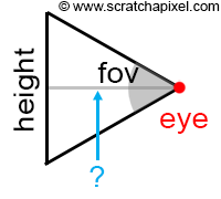
For example, we can look at the problem in the following way: the pixel coordinates don't need to be normalized (in other words, converted from pixel coordinates to NDC and then screen space). We can compute the ray direction using the following equations:
$$ \begin{array}{l} d_x &=& x - width / 2 \\ d_y & = & height / 2 - y\\ d_z & = &-(height / 2) / tan(fov * 0.5). \end{array} $$Where x and y are the pixel's coordinates, and fov is the vertical field-of-view. Keep in mind that \(d_z\) is negative because the camera by default is oriented along the negative z-axis. Then if we normalize this vector, we get the same result as if we had been through a raster to NDC, and NDC-to-screen transform. If we transform this ray direction to world space (we multiply the vector d by the camera-to-world matrix), we get:
$$ \begin{array}{l} d_x &=& (x - width / 2) u_x + (height / 2 - y) v_x - ((height / 2 ) / tan(fov * 0.5)) w_x \\ d_y &=& (x - width / 2) u_y + (height / 2 - y) v_y - ((height . 2)/tan(fov * 0.5)) w_y \\ d_z & = & (x -width /2) u_z + (height / 2 - y) v_z - ((height / 2)/tan(fov * 0.5)) w_z \end{array} $$If we expand and regroup the terms we get:
$$ \begin{array}{l} d_x & = & x u_x - width / 2 u_x + height / 2 v_x - y v_x - (height /2 )/tan(fov * 0.5) w_x \\ & = & x u_x + y (-v_x) + (width / 2 u_x + height / 2 v_x - (height / 2) /tan(fov * 0.5) w_x) \\ d_y & = & x u_y - width / 2 u_y + height / 2 v_y - y v_y - (height /2 )/tan(fov * 0.5) w_y \\ & = & x u_y + y (-v_y) + (width / 2 u_y + height / 2 v_y - (height / 2) /tan(fov * 0.5) w_y) \\ d_z & = & x u_z - width / 2 u_z + height / 2 v_z - y v_z - (height /2 )/tan(fov * 0.5) w_z \\ & = & x u_z + y (-v_z) + (width / 2 u_z + height / 2 v_z - (height / 2) /tan(fov * 0.5) w_z) \end{array} $$Which we can re-write as (equation 1):
$$d = x u + y (-v) + w'.$$Where \( w' = (-width / 2) u + (height / 2) v - ((height / 2) / tan(fov * 0.5)) w.\)
In other words, if we know the camera-to-world matrix, we can pre-compute the w' vector, compute the ray direction in word space using equation 1, and then normalize the resulting vector. In pseudo-code:
Vec3f w_p = (-width / 2 ) * u + (height / 2) * v - ((height / 2) / tan(fov_rad * 0.5);
Vec3f ray_dir = normalize(x * u + y * (-v) + w_p);
The vector w' only needs to be computed once and re-used each time we need to compute a new ray direction. The vectors u, v, and w are just the first, second, and third vectors of the camera-to-world matrix (the first three rows if you use row-major matrices).
Summary: We Are Almost Ready to Render our First Image
As we progress in this series of lessons, will be able to put all the different techniques we learned about so far to create a basic but functional ray-tracer (by functional we mean rendering some geometry and saving the resulting image to a file on disk). All we are now missing to get to that result is to learn about ray-geometry intersection which is the topic of the next lesson.