How a pinhole camera works (part 1)
Reading time: 16 mins.What Will You Learn in This Lesson?
In the previous lesson, we learned about some key concepts involved in the process of generating images. However, we didn't specifically discuss cameras. 3D rendering is not only about producing realistic images through perspective projection but also about being able to deliver images similar to those produced by real-world cameras. Why? Because when CG images are combined with live-action footage, the images delivered by the renderer need to match the images captured by the camera that produced the footage. In this lesson, we will develop a camera model that allows us to simulate results produced by real cameras, using real-world parameters to set the camera. To do so, we will first review how film and photographic cameras work.
More specifically, we will demonstrate in this lesson how to implement a camera model similar to that used in Maya and most (if not all) 3D applications (such as Houdini, 3DS Max, Blender, etc.). We will explain the effect of each control found on a camera on the final image and how to simulate these controls in CG. This lesson will answer all questions you may have about CG cameras, such as what the film aperture parameter does and how the focal length parameter relates to the angle of view parameter.
While the optical laws involved in the process of generating images with a real-world camera are simple, reproducing them in CG can be challenging—not because they are complex, but because they are potentially expensive to simulate. However, you don't need very complex cameras to produce images. In fact, it's quite the opposite. You can take photographs with a very simple imaging device called a pinhole camera, which is just a box with a small hole on one side and photographic film on the other. Images produced by pinhole cameras are much easier to reproduce (and less costly) than those produced with more sophisticated cameras. For this reason, the pinhole camera is the model used by most (if not all) 3D applications and video games. Let's start by reviewing how these cameras work in the real world and build a mathematical model from there.
It is best to understand the pinhole camera model, which is the most commonly used camera model in CG, before getting to the topic of the perspective projection matrix that reuses concepts we will be studying in this lesson, such as the camera angle of view, the clipping planes, etc.
Camera Obscura: How Is an Image Formed?
Most algorithms we use in computer graphics simulate how things work in the real world. This is particularly true for virtual cameras, which are fundamental to the process of creating a computer graphics image. The creation of an image in a real camera is relatively simple to reproduce with a computer. It mainly relies on simulating the way light travels in space and interacts with objects, including camera lenses. The light-matter interaction process is highly complex, but the laws of optics are relatively simple and can easily be simulated in a computer program. There are two main parts to the principle of photography:
-
The process by which an image is stored on film or in a file.
-
The process by which this image is created in the camera.
In computer graphics, we don't need a physical medium to store an image, thus simulating the photochemical processes used in traditional film photography won't be necessary (unless, like the Maxwell renderer, you want to provide a realistic camera model, but this is not necessary to get a basic model working).

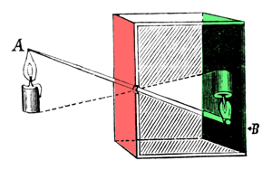
Now, let's talk about the second part of the photography process: how images are formed in the camera. The basic principle behind the image creation process is straightforward, as demonstrated in the reproduction of an illustration published in the early 20th century (Figure 1). In the setup from Figure 1, the first surface (colored red) blocks light from reaching the second surface (colored green). By making a small hole (a pinhole), however, light rays can pass through the first surface at a single point, thereby forming an (inverted) image of the candle on the other side. Following the path of the rays from the candle to the surface onto which the image of the candle is projected illustrates how the image is geometrically constructed. In reality, the image of the candle will be quite faint because the amount of light emitted by the candle and passing through point B is minimal compared to the overall light emitted by the candle itself (only a fraction of the light rays emitted by the flame or reflected off of the candle will pass through the hole).
A camera obscura (Latin for "dark room") operates on the same principle. It is a lightproof box or room with a black interior (to minimize light reflections) and a tiny hole in the center on one end (Figure 2). Light passing through this hole forms an inverted image of the external scene on the opposite side of the box. This simple device led to the development of photographic cameras. You can even convert your room into a camera obscura, as shown in a video by National Geographic (all rights reserved).
To see the projected image on the wall clearly, your eyes first need to adjust to the darkness of the room. To capture this effect with a camera, long exposure times are necessary (ranging from a few seconds to half a minute). To transform your camera obscura into a pinhole camera, simply place a piece of film on the face opposite the pinhole. If you wait long enough (and keep the camera perfectly still), light will alter the chemicals on the film, creating a latent image over time. The principle for a digital camera is similar, but the film is replaced by a sensor that converts light into electrical charges.
How Does a Real Camera Work?
In a real camera, images are created when light falls on a surface sensitive to light (this principle also applies to the eye). For a film camera, this sensitive surface is the film; for a digital camera, it is the sensor (or CCD). Some of these concepts were introduced in the lesson Introduction to Ray-Tracing, and we will briefly revisit them here.

Light in the real world emanates from various sources, with the sun being the most significant. When light strikes an object, it may either be absorbed or reflected into the scene. This phenomenon is explored in depth in the lesson devoted to light-matter interaction, available in the Mathematics and Physics for Computer Graphics section. When you take a picture, some of that reflected light (in the form of photon packets) travels towards the camera and passes through the pinhole, forming a sharp image on the film or the digital camera sensor, as shown in Figure 3.
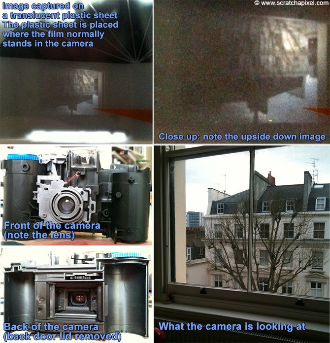
Many documents on how photographic film works can be found on the internet. It's worth noting that film exposed to light does not immediately create a visible image. Instead, it produces what is known as a latent image (invisible to the eye), and we need to process the film with chemicals in a darkroom to make the image visible. If you replace the back door of a disposable camera with a translucent plastic sheet, you should be able to see the inverted image that is normally projected onto the film.
Pinhole Cameras
The simplest type of camera found in the real world is the pinhole camera. It consists of a simple, lightproof box with a very small hole in the front, known as an aperture, and some light-sensitive film or paper placed inside the box on the side facing this pinhole. To take a picture, you simply open the aperture to expose the film to light. To prevent light from entering the box when not in use, a piece of opaque tape covers the pinhole; this is removed to take the photograph and replaced afterward.

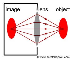
The principle of a pinhole camera is straightforward. Objects in the scene reflect light in all directions. The aperture's size is so small that, among the many rays reflected off at P, a point on the surface of an object in the scene, only a narrow beam of light rays or photons enters the camera. While in reality, it's never exactly one ray but more a bundle of light rays, this simplification helps understand the concept. In Figure 3, we can see how a single light ray among the many reflected at P passes through the aperture. In Figure 4, six of these rays are colored to track their path to the film plane more easily, demonstrating how they form an image of the object rotated by 180 degrees. The pinhole is also referred to as the center of projection in geometry; all rays entering the camera converge at this point and diverge from it on the other side.
To summarize, light striking an object is reflected in random directions within the scene. However, only a bundle of these rays traveling along the same direction enters the camera and strikes the film at a single point. To each point in the scene corresponds a single point on the film.
The explanation above utilizes the concept of "point" to describe what happens locally at an object's surface and at the film's surface. However, it's crucial to remember that the surface of objects is continuous (at least at the macroscopic level), making the image of these objects on the film also appear continuous. What is referred to as a "point" for simplification is actually a small area on an object's surface or on the film. Ideally, the process would be described as an exchange of light energy between surfaces (the emitting surface of the object and the receiving surface of the film), but for simplicity, these small surfaces are treated as points.
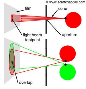
The size of the aperture is crucial. For a sharp image, each point (or small area) on an object's surface needs to be represented by a single point (another small area) on the film. As mentioned before, what passes through the hole is not exactly one ray but rather a small set of rays contained within a cone of directions. The angle of this cone, or more precisely, its angular diameter, depends on the size of the hole, as shown in Figure 6.

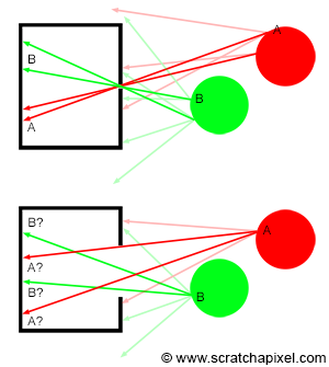
The smaller the pinhole, the sharper the image. However, a smaller pinhole necessitates a longer exposure time because the amount of light passing through and striking the film surface decreases as the hole diminishes in size. A certain amount of light is required for an image to form on photographic paper; thus, the lesser the light received, the longer the exposure time needed. While not an issue for CG cameras, for real pinhole cameras, longer exposure times increase the risk of blurred images if the camera isn't perfectly still or if objects within the scene move. Generally, shorter exposure times are preferable. Yet, there's a limit to how small the pinhole can be. When it becomes very small—approximately the size of the light's wavelength—diffraction occurs, which is undesirable. For a shoebox-sized pinhole camera, a pinhole diameter of about 2 mm is optimal, balancing image focus and exposure time. Note that with too large an aperture (as shown in Figure 5, bottom), a point on the image—when conceptualized as discrete lines or points of light (for example, point A or B in Figure 5)—appears multiple times, causing blurriness. This is more accurately visualized as the overlapping footprints of light cones on the film (Figure 6, bottom). As the pinhole enlarges, so do the cones, increasing overlap. This multiplicity (the cone's footprint or spot enlarging on the film, spreading the originating light's color over a larger region rather than a singular point as theoretically should occur) leads to blurred or out-of-focus images. This effect is particularly noticeable when photographing small, bright objects against a dark background, like fairy lights at night (Figure 8), where the generated disks are clearly visible. In photography, these disks—though not always perfectly circular—are known as circles of confusion, among other terms.
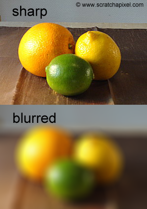
To further elucidate the image formation process, two short animations were created. The first animation (Figure 9) depicts a small pinhole, resulting in a sharp image of the disks because each object point corresponds to a single point on the film.

The second animation demonstrates the consequences of using a pinhole that is too large. In this scenario, each point on the object is represented by multiple points on the film, resulting in a blurred image of the disks.
In conclusion, to produce a sharp image, we must ensure the aperture of the pinhole camera is as small as possible. This minimizes the aperture to allow only a narrow beam of photons from a single direction to enter the camera and impact the film or sensor at a single point (or as small a surface as possible). The ideal pinhole camera would have an aperture so minuscule that only a single light ray from each point in the scene enters the camera. However, such a camera cannot be constructed in the real world due to diffraction issues when the aperture becomes too small. In contrast, in the virtual world of computers, where light rays are not subject to diffraction, an ideal pinhole camera can exist. Renderers using this ideal model produce images of 3D scenes with perfect sharpness.

In photography, depth of field (DOF) refers to the range between the closest and furthest objects in a scene that appear "reasonably" sharp in an image. Unlike cameras with lenses, pinhole cameras have an infinite depth of field, meaning the sharpness of objects is not influenced by their distance from the camera. Computer graphics often employ the ideal pinhole camera model, resulting in an infinite depth of field where all visible scene objects through the camera are rendered with perfect sharpness. This has led to criticism of computer-generated images for being overly clean and sharp, a characteristic largely attributed to this camera model. However, simulating depth of field is relatively straightforward and is covered in a dedicated lesson within this section.
When the pinhole is very small, only a minimal amount of light can pass through the aperture, necessitating long exposure times. This is a limitation when aiming to produce sharp images of moving subjects or in low-light conditions. Naturally, a larger aperture allows more light to enter the camera but at the cost of increased blurriness. Introducing a lens in front of the aperture can refocus the light rays onto a single point on the film plane, mitigating this issue. This lesson serves as an introduction to pinhole cameras rather than a comprehensive explanation of camera mechanics and the role of lenses in photography. Further information on this topic is available in the lesson devoted to depth of field. It's noteworthy that lenses are used in modern cameras to enlarge the aperture, thereby reducing exposure times while avoiding the blur associated with large pinholes. Lenses refocus light reflected from object surfaces back to single points on the film, combining the benefits of a large aperture with those of a lens to achieve both short exposure times and sharp images. However, lens use introduces depth of field, a topic beyond the scope of this lesson. Pinhole cameras, prized for their simplicity, do not require lenses, making them easy to build and simulate in computer graphics.