How Does it Work
Reading time: 8 mins.Scratchapixel is tailored for beginners with minimal background in mathematics or physics. We aim to explain everything from the ground up in straightforward English, accompanied by coding examples to demonstrate the practical application of theoretical concepts.
This lesson is perfectly suited for those merely curious about computer-generated 3D graphics without the intention of pursuing a career in this field. It is designed to be self-explanatory, packed with sufficient information, and includes a simple, compilable program that facilitates a comprehensive understanding of the concept. With this knowledge, you can acknowledge your familiarity with the subject and proceed with your life or, if inspired by CGI, delve deeper into the field—a domain fueled by passion, where creating meaningful computer-generated pixels is nothing short of extraordinary. More lessons await those interested to expand their understanding and skills in CGI programming.
This lesson offers a comprehensive introduction to the realm of 3D computer graphics programming, focusing specifically on one key area: 3D rendering, particularly through the lens of the ray-tracing algorithm. When delving into the world of 3D graphics, particularly in the context of computer graphics programming, it seems most intuitive to begin by grasping how a three-dimensional scene is transformed into a two-dimensional image for display. This rationale guides our approach, yet it's important to acknowledge that computer graphics spans beyond just rendering. We will explore these additional dimensions, such as animation, simulation, and image processing, in more detailed and advanced lessons later on. We will learn about alternative rendering techniques, such as scanline rendering, which remains the predominant method for image generation via GPUs as well as about a wide range of other techniques used in the process of making 3D films and video games.
Since its inception as Scratchapixel's very first lesson in 2009, this lesson has become renowned as a leading introductory resource on ray-tracing across the internet. Yet, it's vital to emphasize once more that our main objective here is not to delve deeply into teaching ray-tracing. Instead, ray-tracing and 3D rendering serve more as vehicles to introduce newcomers to the vast domain of computer graphics, aiming to furnish a broad understanding of its mechanics. For those particularly intrigued by the ray-tracing technique, we recommend our lesson, An Overview of the Ray-Tracing Rendering Technique, for a more focused exploration.
Additionally, a key goal of this introductory computer graphics lesson is to provide you with a practical program that you can compile and execute. This strategy is designed to ignite enthusiasm for engaging with hands-on projects just as much as for the underlying theory. It plays a crucial role in sustaining motivation and showcasing that mastering computer graphics programming is attainable. Opting to generate an image through ray-tracing is just one of many possible paths we could have chosen. However it is feasible to develop a ray-tracer with just a few hundred lines of code, striking an ideal balance between coding simplicity and the rewarding visual results it produces. This, too, justifies our selection of this technique for an introductory lesson..
The creation of computer graphics as we shall see, often mimics natural phenomena (occasionally in reverse order), though surpassing nature's complexity is a feat yet to be achieved by humans – a limitation that, nevertheless, does not diminish the enjoyment derived from these endeavors.
Let's embark on this journey together...
How Is an Image Created?
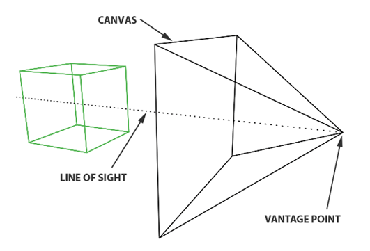
The creation of an image necessitates a two-dimensional surface, which acts as the medium for projection. Conceptually, this can be imagined as slicing through a pyramid, with the apex positioned at the viewer's eye and extending in the direction of the line of sight. This conceptual slice is termed the image plane, akin to a canvas for artists. It serves as the stage upon which the three-dimensional scene is projected to form a two-dimensional image. This fundamental principle underlies the image creation process across various mediums, from the photographic film or digital sensor in cameras to the traditional canvas of painters, illustrating the universal application of this concept in visual representation.
Perspective Projection
Perspective projection is a technique that translates three-dimensional objects onto a two-dimensional plane, creating the illusion of depth and space on a flat surface. Imagine wanting to depict a cube on a blank canvas. The process begins by drawing lines from each corner of the cube towards the viewer's eye. Where each line intersects the image plane—a flat surface akin to a canvas or the screen of a camera—a mark is made. For instance, if a cube corner labeled c0 connects to corners c1, c2, and c3, their projection onto the canvas results in points c0', c1', c2', and c3'. Lines are then drawn between these projected points on the canvas to represent the cube's edges, such as from c0' to c1' and from c0' to c2'.
Repeating this procedure for all cube edges yields a two-dimensional depiction of the cube. This method, known as perspective projection, was mastered by painters in the early 15th century and allows for the representation of a scene from a specific viewpoint.
Light and Color
After mastering the technique of sketching the outlines of three-dimensional objects onto a two-dimensional surface, the next step in creating a vivid image involves the addition of color.
Briefly recapping our learning: the process of transforming a three-dimensional scene into an image unfolds in two primary steps. Initially, we project the contours of the three-dimensional objects onto a two-dimensional plane, known as the image surface or image plane. This involves drawing lines from the object's edges to the observer's viewpoint and marking where these lines intersect with the image plane, thereby sketching the object's outline—a purely geometric task. Following this, the second step involves coloring within these outlines, a technique referred to as shading, which brings the image to life.
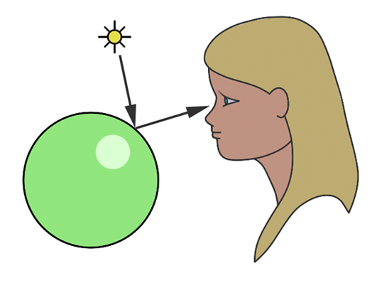
The color and brightness of an object within a scene are predominantly determined by how light interacts with the material of the object. Light consists of photons, electromagnetic particles that embody both electric and magnetic properties. These particles carry energy and oscillate similarly to sound waves, traveling in direct lines. Sunlight is a prime example of a natural light source emitting photons. When photons encounter an object, they can be absorbed, reflected, or transmitted, with the outcome varying depending on the material's properties. However, a universal principle across all materials is the conservation of photon count: the sum of absorbed, reflected, and transmitted photons must equal the initial number of incoming photons. For instance, if 100 photons illuminate an object's surface, the distribution of absorbed and reflected photons must total 100, ensuring energy conservation.
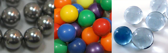
Materials are broadly categorized into two types: conductors, which are metals, and dielectrics, encompassing non-metals such as glass, plastic, wood, and water. Interestingly, dielectrics are insulators of electricity, with even pure water acting as an insulator. These materials may vary in their transparency, with some being completely opaque and others transparent to certain wavelengths of electromagnetic radiation, like X-rays penetrating human tissue.
Moreover, materials can be composite or layered, combining different properties. For example, a wooden object might be coated with a transparent layer of varnish, giving it a simultaneously diffuse and glossy appearance, similar to the effect seen on colored plastic balls. This complexity in material composition adds depth and realism to the rendered scene by mimicking the multifaceted interactions between light and surfaces in the real world.
Focusing on opaque and diffuse materials simplifies the understanding of how objects acquire their color. The color perception of an object under white light, which is composed of red, blue, and green photons, is determined by which photons are absorbed and which are reflected. For instance, a red object under white light appears red because it absorbs the blue and green photons while reflecting the red photons. The visibility of the object is due to the reflected red photons reaching our eyes, where each point on the object's surface disperses light rays in all directions. However, only the rays that strike our eyes perpendicularly are perceived, converted by the photoreceptors in our eyes into neural signals. These signals are then processed by our brain, enabling us to discern different colors and shades, though the exact mechanisms of this process are complex and still being explored. This explanation offers a simplified view of the intricate phenomena involved, with further details available in specialized lessons on color in the field of computer graphics.
The understanding of light and how we perceive it has evolved significantly over time. Ancient Greek philosophers posited that vision occurred through beams of light emitted from the eyes, interacting with the environment. Contrary to this, the Arab scholar Ibn al-Haytham (c. 965-1039) introduced a groundbreaking theory, explaining that vision results from light rays originating from luminous bodies like the sun, reflecting off objects and into our eyes, thereby forming visual images. This model marked a pivotal shift in the comprehension of light and vision, laying the groundwork for the modern scientific approach to studying light behavior. As we delve into simulating these natural processes with computers, these historical insights provide a rich context for the development of realistic rendering techniques in computer graphics.