How a pinhole camera works (part 2)
Reading time: 20 mins.In the first chapter of this lesson, we introduced the principle of a pinhole camera. In this chapter, we will demonstrate that the size of the photographic film onto which the image is projected and the distance between the hole and the back side of the box play a crucial role in how a camera captures images. One application of CGI is the blending of CG images with live-action footage. Thus, it's essential for our virtual camera to produce images akin to those captured by a real camera, ensuring seamless compositing between the two systems. Utilizing the pinhole camera model, we will examine the impact of altering the film size and the distance between the photographic paper and the hole on the image quality. In subsequent chapters, we will explore how these adjustments can be incorporated into our virtual camera model.
Focal Length, Angle Of View, and Field of View
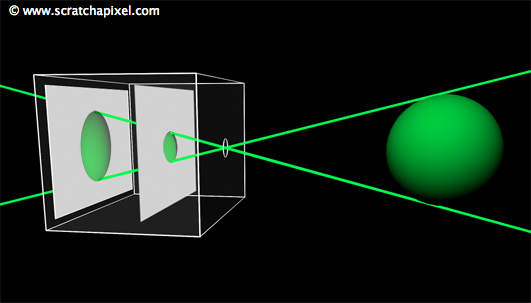
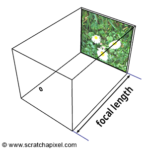
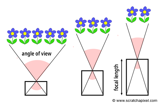
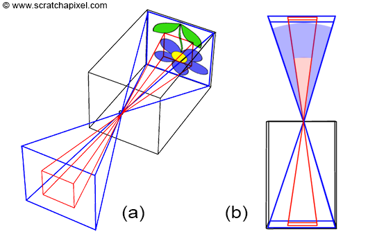
Similar to real-world cameras, our camera model requires a mechanism to control the extent of the scene visible from a given point of view. Revisiting our pinhole camera, the back face of the camera, onto which the scene's image is projected, is termed the image plane. When this plane is moved closer to the aperture, objects appear smaller, and a larger portion of the scene is projected, equating to zooming out. Conversely, moving the film plane away from the aperture captures a smaller portion of the scene, or zooming in (as illustrated in Figure 1). This feature can be quantified in two ways: the distance from the film plane to the aperture, which can be adjusted to vary the scene's coverage on film, commonly referred to as the focal length or focal distance (Figure 2), or by varying the angle (increasing or decreasing) at the apex of a triangle defined by the aperture and the film edges (Figures 3 and 4), known as the angle of view or field of view (AOV and FOV, respectively).
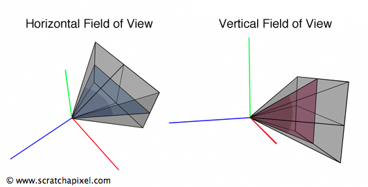
In 3D graphics, the extent of the scene visible through the camera can be determined by a triangle connecting the aperture to either the top and bottom edges of the film, defining the vertical field of view, or to the left and right edges, defining the horizontal field of view (Figure 4). Notably, rendering APIs do not adhere to a single convention: for instance, OpenGL employs a vertical FOV, while RenderMan Interface and Maya utilize a horizontal FOV.
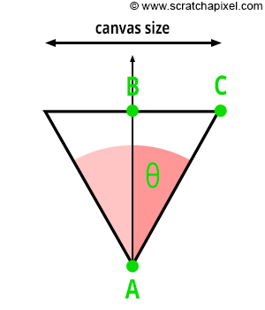
As depicted in Figure 3, a direct relationship exists between the focal length and the angle of view. Let's denote AB as the distance from the eye to the canvas—while this distance is typically assumed to be 1, we must consider more general cases. Let BC represent half the canvas size (width or height), and \(\theta\) denote half the angle of view. Given that ABC forms a right triangle, we can apply Pythagorean trigonometric identities to calculate BC if we know both \(\theta\) and AB:
$$ \begin{align*} \tan(\theta) &= \frac{BC}{AB} \\ BC &= \tan(\theta) \times AB \\ \text{Canvas Size} &= 2 \times \tan(\theta) \times AB \\ \text{Canvas Size} &= 2 \times \tan(\theta) \times \text{Distance to Canvas}. \end{align*} $$This relationship is crucial for controlling the size of objects within the camera's field of view by adjusting a single parameter—the angle of view. As we've discussed, altering the angle of view modifies the portion of the scene captured by the camera, a phenomenon commonly known in photography as zooming in or out.
Film Size Matters Too
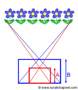
As illustrated in Figure 6, the extent of the scene we capture also depends on the film (or sensor) size. In photography, the size of the film or image sensor is significant. A larger surface (in blue) captures a wider extent of the scene than a smaller surface (in red). Consequently, a relationship exists between the film's size and the camera's angle of view: the smaller the surface, the narrower the angle of view (as shown in Figure 6).
Caution is advised, as confusion sometimes arises between film size and image quality. Of course, there is a relationship between the two. The development of large formats, in both film and photography, was primarily driven by image quality considerations. The larger the film, the greater the detail and the better the image quality. However, it's important to note that when using films of different sizes while aiming to capture the same scene extent, you must adjust the focal length accordingly (as demonstrated in Figure 7). That's why a 35mm camera with a 50mm lens doesn't produce the same image as a large format camera with a 50mm lens, where the film size is at least three times larger than a 35mm film. The focal length is the same in both cases, but due to the differing film sizes, the angular extent of the scene captured by the large format camera is larger than that of the 35mm camera. It's crucial to remember that the surface size capturing the image (whether digital or film) also determines the angle of view, in addition to the focal length.
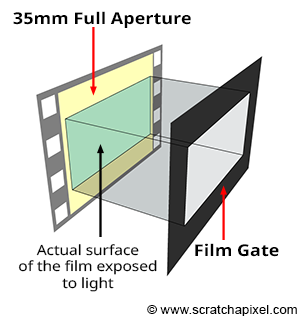
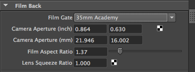
The terms film back and film gate technically refer to slightly different things, but both relate to film size, which is why the terms are often used interchangeably. The former term pertains to the film holder, a device generally placed at the back of the camera to hold the film. The latter designates a rectangular opening in front of the film. By adjusting the gate size, we can change the area of the 35mm film exposed to light. This modification enables the film format to be changed without altering the camera or the film. For instance, CinemaScope and Widescreen are formats shot on 35mm 4-perf film with a film gate. Note that film gates are also utilized with digital film cameras, defining the film's aspect ratio.
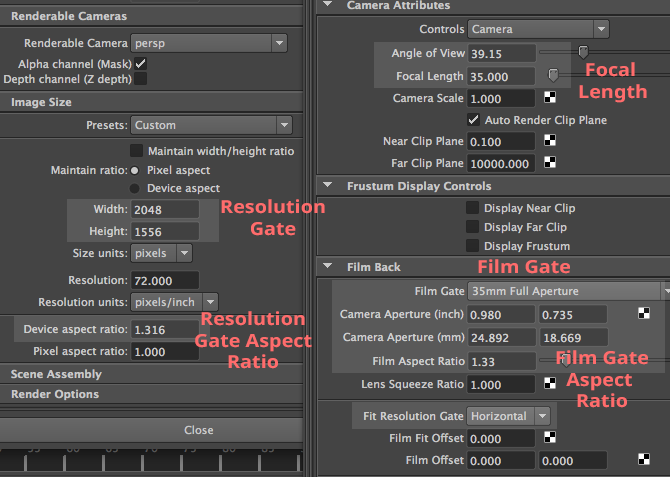
The 3D application Maya consolidates all these parameters in a "Film Back" section. Changing the Film Gate parameter, which can be any predefined film format such as 35mm Academy (the most commonly used format in film) or any custom format, alters the Camera Aperture parameter. This parameter specifies the horizontal and vertical dimensions (in inches or mm) of the film. The Film Aspect Ratio, visible under the Camera Aperture parameter, is the ratio between the film's "physical" width and height. See the list of film formats for a compilation of available formats.
At this chapter's end, we will explore the relationship between the film aspect ratio and the image aspect ratio.
It's essential to understand that the angle of view is determined by two critical parameters: the focal length and the film size. Altering either one of these parameters affects the angle of view:
-
When the film size is fixed, altering the focal length changes the angle of view. A longer focal length results in a narrower angle of view.
-
When the focal length is fixed, changing the film size alters the angle of view. A larger film leads to a wider angle of view.
-
To modify the film size while maintaining the same angle of view, you must adjust the focal length accordingly.
It's noteworthy that three parameters—the angle of view, the focal length, and the film size—are interconnected. With two known parameters, the third can be inferred. Given the focal length and film size, you can calculate the angle of view; knowing the angle of view and film size allows you to compute the focal length. The subsequent chapter will present the mathematical equations and code for these calculations. Nevertheless, if calculating the angle of view from the film size and focal length seems daunting, it's not obligatory; you may directly input a value for the angle of view into your program. However, our objective in this lesson is to emulate a real physical camera accurately, taking both parameters into account.
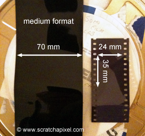
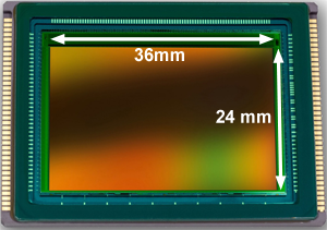
The selection of a film format typically balances cost, camera workability (the larger the film, the larger the camera), and the required image definition. The most widely used film format for still photography was (and remains) 36 mm (1.4 in) wide, known more commonly as the 24 by 35 mm format, though the exact horizontal image size is 36 mm. Following 35 mm film, the medium format film is larger (usually 6 by 7 cm), and large format refers to any imaging format of 4 by 5 inches or larger. Film formats in filmmaking vary significantly in size. It's a misconception to think that the advent of digital cameras eliminates concerns about film size. In digital cameras, the sensor size replaces film size, influencing the scene's captured extent. High-end digital DSLR cameras, like the Canon 1D or 5D, feature sensors with dimensions matching the 135 film format: 36 mm in width and 24 mm in height (Figure 8).
Image Resolution and Frame Aspect Ratio
The size of a film (measured in inches or millimeters) should not be confused with the number of pixels in a digital image. While the film's size impacts the angle of view, image resolution—the number of pixels in an image—does not. These two camera properties (the size of the image sensor and the number of pixels on it) are independent.
In digital cameras, film is replaced by a sensor, a device that captures light and converts it into an image, serving as the electronic equivalent of film. Image quality depends on both the size of the sensor and the number of pixels it contains. It's crucial to understand that film size is analogous to sensor size, playing the same role in defining the angle of view (Figure 9). However, the number of pixels on the sensor, which determines image resolution, does not affect the angle and is specific to digital cameras. Pixel resolution only influences image clarity.
This concept also applies to CG images, where different image resolutions can represent the same scene. While these images appear similar (assuming the width-to-height ratio remains constant), higher resolutions provide more detail. The resolution of the frame, expressed in pixels, is denoted by width and height resolution, indicating the number of pixels along the horizontal and vertical dimensions, respectively. The image can be likened to a gate, hence the term resolution gate used in Maya. This chapter concludes by examining discrepancies between resolution and film gate relative sizes.
The image aspect ratio, or device aspect ratio in CG, can be calculated from the image resolution as follows:
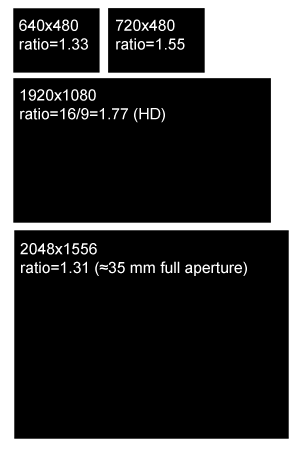
$$\text{Image (or Device) Aspect Ratio} = \frac{width}{height}$$An aspect ratio greater than 1 indicates the width resolution exceeds the height resolution, and vice versa. This metric is significant, as films and display devices like screens or televisions adhere to standard aspect ratios. Common aspect ratios include:
-
4:3: Used by older television systems and monitors until around 2003, it remains a default on many digital cameras. While associated with older technologies, the 35mm film format, with an aspect ratio of 4:3 (frame dimensions of 0.980x0.735 inches), proves its ongoing relevance in film.
-
5:3 and 1.85:1: Two prevalent standard image ratios in filmmaking.
-
16:9: The standard for high-definition televisions, monitors, and laptops today, usually at a resolution of 1920x1080.
A little bit of history: The RenderMan Interface specifications set the default image resolution to 640 by 480 pixels, resulting in a 4:3 image aspect ratio. The 640x480 pixel resolution, often referred to as VGA (Video Graphics Array) resolution, was a standard in the late 1980s and 1990s. Introduced by IBM in 1987, VGA became the de facto standard for computer graphics hardware.
Canvas Size and Image Resolution: Mind the Aspect Ratio!
Digital images possess a unique characteristic that physical film does not—the aspect ratio of the sensor or the canvas (the 2D surface on which the image of a 3D scene is drawn) can differ from the aspect ratio of the digital image. You might wonder, "Why would that ever be desired?" Generally, it isn't something we aim for, and we'll explain why. Yet, it occurs more frequently than one might expect. Film frames are often scanned with a gate different from the one they were shot with, leading to this discrepancy. This situation also arises when working with anamorphic formats, which we will discuss later in this chapter.
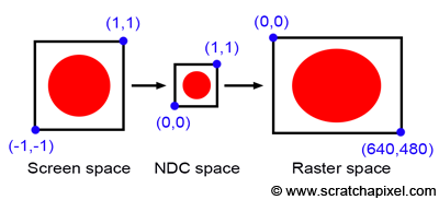
Before delving into anamorphic formats, let's consider the case where the canvas aspect ratio differs from the image or device aspect ratio. Take a simple example where the canvas is a square and the image on it is a circle, with the canvas corners defined as [-1,1] and [1,1]. The process from screen space to raster space involves converting pixel coordinates first to NDC (Normalized Device Coordinates) space and then to raster space, where the canvas is remapped to a unit square. Since both the canvas and the NDC "screen" are square (aspect ratio 1:1), the "image aspect ratio" is preserved, preventing the image from being stretched in either direction. However, if the final image resolution is 640x480, the originally square image (aspect ratio 1:1) is now mapped to a raster image with a 4:3 ratio, causing our circle to stretch into an oval along the x-axis (as depicted in Figure 11). Not preserving the canvas aspect ratio in relation to the raster image aspect ratio leads to image distortion.
You might think again, "Why would this discrepancy occur?" Typically, it doesn't, because, as we'll see in the next chapter, the canvas aspect ratio is often directly derived from the image aspect ratio. Thus, if your image resolution is 640x480, the canvas aspect ratio would be set to 4:3.
However, if you calculate the canvas aspect ratio based on the film size (referred to as Film Aperture in Maya) rather than the image size, rendering the image at a resolution with a different aspect ratio can result in a mismatch. For instance, a 35mm film format (academy size) has dimensions of 22mm by 16mm, yielding an aspect ratio of 1.375. Yet, a standard 2K scan of a full 35mm film frame produces a device aspect ratio of 1.31, leading to differing canvas and device aspect ratios. To address this, software like Maya offers strategies for aligning the canvas ratio with the device aspect ratio at render time:
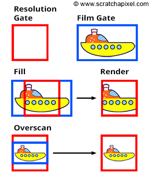
-
The Fill mode forces the resolution gate within the film gate.
-
The Overscan mode forces the film gate within the resolution gate.
These modes are illustrated in Figure 12. If the resolution gate matches the film gate, switching modes has no impact. However, when they differ, the overscan mode causes objects to appear smaller than in the fill mode. This functionality will be implemented in our program (detailed in the last two chapters of this lesson).
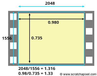
The Kodak standard for scanning a frame from a 35mm film in 2K is 2048x1556. The resulting 1.31 aspect ratio is slightly lower than the actual film aspect ratio of a full aperture 35mm film, which is 1.33 (the dimensions of the frame are 0.980x0.735 inches). This means that we scan slightly more of the film than what's strictly necessary for height (as shown in the adjacent image). Thus, if you set your camera aperture to "35mm Full Aperture" but render your CG renders at a resolution of 2048x1556 to match the resolution of your 2K scans, the resolution and film aspect ratio won't match. In this case, because the actual film gate fits within the resolution gate during the scanning process, you need to select the "Overscan" mode to render your CG images. This means you will render slightly more than you need at the frame's top and bottom. Once your CG images are rendered, you will be able to composite them with your 2K scan. But you will need to crop your composited images to 2048x1536 to return to a 1.33 aspect ratio if required (to match the 35mm Full Aperture ratio). Another solution is scanning your 2K images exactly to 2048x1536 (1.33 aspect ratio), another common choice. That way, both the film gate and the resolution gate match.
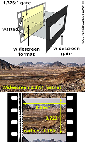
The only exception to keeping the canvas and image aspect ratio the same is when working with anamorphic formats. The concept is straightforward. Traditional 35mm film cameras have a 1.375:1 gate ratio. To shoot with a widescreen ratio, you need to place a gate in front of the film (as shown in the adjacent image). However, this means part of the film is wasted. You can use a special lens called an anamorphic lens, which compresses the image horizontally to fit as much of the 1.375:1 gate ratio as possible. When the film is projected, another lens stretches the images back to their original proportions. The main benefit of shooting anamorphic is the increased resolution (since the image uses a larger portion of the film). Typically, anamorphic lenses squeeze the image by a factor of two. For instance, Star Wars (1977) was filmed in a 2.35:1 ratio using an anamorphic camera lens. If you were to composite CG renders into Star Wars footage, you would need to set the resolution gate aspect ratio to approximately 4:3 (the lens squeezes the image by a factor of 2; if the image ratio is 2:35, then the film ratio is closer to 1.175), and the "film" aspect ratio (the canvas aspect ratio) to 2.35:1. In CG, this is typically achieved by changing what we call the pixel aspect ratio. In Maya, there is also a parameter in the camera controls called Lens Squeeze Ratio, which has the same effect. But this topic is for another lesson.
Conclusion and Summary: Everything You Need to Know about Cameras
The key takeaway from the last chapter is that the camera's angle of view ultimately determines the visual outcome. You can directly set its value to achieve the desired visual effect.
I want to combine real film footage with CG elements. The real footage is shot and loaded into Maya as an image plane. Now I want to set up the camera (manually) and create some rough 3D surroundings. I noted down a couple of camera parameters during the shooting and tried to feed them into Maya, but it didn't work out. For example, if I enter the focal length, the resulting view field is too big. I need to familiarize myself with the relationship between focal length, film gate, field of view, etc. How do you tune a camera in Maya to match a real camera? How should I tune a camera to match these settings?
If your objective is to develop a camera model that emulates physical cameras, as in the example above, you'll need to calculate the angle of view by taking into account both the focal length and the film gate size. Applications like Maya provide access to these controls (illustrated in the screenshot below of Maya's UI, showing Render Settings and Camera attributes), enabling you to understand their purpose, their effect, and how to adjust their values to replicate the output of a real camera. For integrating CG images with live-action footage, you should be aware of the following:
-
Film Gate Size: This is usually specified in inches or mm and can always be found in camera specifications.
-
Focal Length: It's crucial to remember that the angle of view is influenced by the film size at a given focal length. That means if you maintain the focal length but alter the film aperture, the object size within the camera's view will change.
However, it's vital to recall that the resolution gate ratio might differ from the film gate ratio, which is only desirable when working with anamorphic formats. For instance, if the resolution gate ratio of your scan is narrower than the film gate ratio, you should set the Fit Resolution Gate parameter to Overscan, as in the case of 2K scans of 35mm full aperture film, where the ratio (1.316:1) is less than the actual frame ratio (1.375:1). This detail requires careful attention for CG renders to align with the footage accurately.
Ultimately, the "film gate ratio" only differs from the "resolution gate ratio" when dealing with anamorphic formats, which is relatively rare.
What's Next?
We're now prepared to construct a virtual camera model that can produce images consistent with those from real-world pinhole cameras. In the upcoming chapter, we'll demonstrate that ray tracing requires only the angle of view. However, with the rasterization algorithm, both the angle of view and the canvas size are necessary. The reasons for this and the methods to calculate these values will be discussed in the next chapter, with detailed computations following in chapter four.