Lights
Reading time: 10 mins.This lesson was written sometime in the early 2010s. It was intended as a lightweight introduction to some of the most basic concepts in shading. While this chapter is still valid, it might serve as a good introduction to lights or for people who do not wish to study this topic much further. Readers interested in a much more in-depth lesson on lights in computer graphics are invited to read the following lessons: A Creative Dive into BRDF, Linearity, and Exposure and Introduction to Lighting, with the latter being published for the first time in 2024.
Lights
Before we look into producing our first shaded image, we first need to introduce the concept of light. As mentioned in previous lessons, a scene is composed of a camera, objects, and lights. Lights are special "entities" whose only function is to indicate where light is emitted from in the scene. As mentioned before, the only reason why we see objects is that light emitted by light sources bounces off the surfaces of objects. If you don't create a light in the scene, the scene should be rendered black.

In the real world, every light source has a physical body. Light sources are objects that have the property to emit light. However, a light source is nothing else than a standard object: it has a shape and a size. Though, it has a property that other objects don't have: it emits light. Because light sources are objects in their own right, they can also be directly seen by the eyes. However, generally, never look at light sources directly with the naked eye as it can be harmful. Looking at the sun directly, yes, will burn your eyes. However, we can contemplate other sources of light safely, such as the flames of a campfire or the light bulb of a torch. If you are reading these lines, you are even looking at one just now: the screen of your phone or computer. The problem is that in CG, simulating light in a physically accurate way, that is by representing them as objects with their shape and size, is computationally expensive. Such lights are called area lights or more generally, geometric area lights. For this reason, lights in CG have for a very long time only been represented as idealized objects, that is, as entities with no physical size. In opposition to area lights, such lights are also sometimes called delta lights (from the term delta function, which is a special function in mathematics that was created to sort of define a function that can't exist in nature but does exist in the abstract world of mathematics. Although abstract, it is super useful to solve all sorts of interesting and practical problems). We can differentiate essentially two types of delta lights: directional or distant lights and spherical lights or point light sources. The former is generally a subset of the latter, but we will explain this in a moment.
You need to know: Delta lights were used in the early days of computer graphics for practical reasons because simulating area lights for a very long time was too expensive. As computers became faster in the late 2000s, it also slowly became practically possible to switch to area lights. Using delta lights, especially today, should be avoided as much as possible. Why? Because not representing light as area lights causes a lot of problems. For example, we know that objects reflect other objects and of course, light sources, since they are objects in their own right, should also be reflected by glossy surfaces or mirrors, for instance. Though the size of the reflection of an object by a glossy surface depends on the reflected object's size and distance to the glossy surface (these two concepts, the size of the object and the distance of the reflected object to the reflective surface can be combined into the concept of solid angle, which we won't talk about much in this lesson. For more information on this topic, please check the lessons from the advanced sections).
When lights have no size, then it is simply impossible to decide how big their reflection on a glossy surface should be! This has caused a lot of problems in the field of rendering for many years. People had to use hacks to control the size of these reflections by adjusting the roughness of the reflective surface as well as artificially controlling that roughness by adjusting a "roughness" parameter on the light itself. Doing so would help you cheat the size of the light on a per-light basis, but this could certainly never lead to producing physically accurate images. Hopefully, such practices have almost entirely disappeared these days, mostly because simulating area lights, as just mentioned, is now affordable (though simulating area lights is still computationally expensive and requires careful optimizations).
Using area lights is a condition to physically based rendering or PBR, which is a term you may be already familiar with. This topic is covered in great detail in the lessons from the advanced sections. You can also find more information about it in the last lesson of this section.
Distant Lights
Distant lights are considered so far away that the light they emit reaches us as parallel rays. With such light sources, the only relevant factor is the direction of these light rays. An example of a distant light is the sun. While the sun is a sphere and might be thought of as a spherical light, at the scale of the solar system or even larger scales, yes, it acts as a spherical light. However, as illustrated in the image below, the Earth is small compared to the sun and significantly far from the star, so that the sunlight reaching the Earth's surface is contained within a super narrow cone of directions.


The solid angle of this cone, for readers familiar with the concept, is only approximately 0.0000687 steradians. In CG, when we render a scene covering only a small area of the Earth's surface, we can safely assume that the sun rays illuminating that scene are all parallel. There might be a negligible variation, but it is so minor that we can ignore it altogether. We likely will never have enough numerical precision to represent this variation accurately. In simple terms: we don't care. Sun rays hitting the Earth's surface are parallel. Consequently, all we care about in this case is the light rays' direction, hence the term directional light. The position of the light source relative to the rendered scene is irrelevant because the only reason the rays are parallel is that the source is extremely far from the scene, and thus the rays are contained in a tiny cone of directions, leading to the term distant light. Essentially, all we need in CG to simulate the sun or any other distant light is a direction and nothing else.
Note, the sun is very far away but it has a noticeable size in the sky. In fact, as surprising as it may seem, the sun appears larger in the sky than the moon.
In this lesson, we will first render diffuse objects and learn how to cast shadows using distant lights. We will then learn how to simulate spherical lights.
Spherical Light Sources
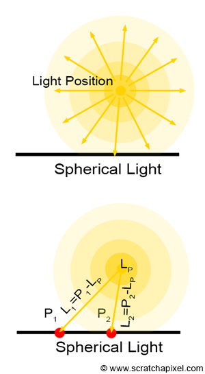
Spherical light sources are the most common type of light found in nature. To some extent, even lights that are not spherical can be approximated as a collection of spherical light sources. Unlike distant light sources, the position of spherical lights is crucial. In fact, for spherical light sources, this is the only thing that matters. We need to know where they are in space. If \(P\) is a point on the surface of an object that we want to shade, then finding the direction of the ray that a spherical light source emits towards \(P\) is simple: it is merely \(P\) minus the spherical light position (let's call it \(L_P\)), as shown in Figure 2.
$$\text{Light Direction} = P - L_P.$$In the subsequent chapters, we will show that the distance between \(P\) and the light source also matters (for a spherical light but not for a distant light, the amount of light illuminating an object depends on the distance between the light and the object). We will need this distance, which we will then use to normalize the light direction vector. This will be explained later in the lesson.
Light Intensity (and Color)
Beyond the position of the light (if it is a spherical or point light source) or the direction of the light (if it is a distant or directional light), what else do we need to define a light source? In computer graphics, light sources emit light, which we can represent as a combination of color and intensity. It is generally best to define the light color with values in the range [0,1] and the light intensity with values from 0 to infinity (or up to the maximum value representable by a floating point in computer code). The final amount of emitted light is calculated by multiplying the light color by its intensity:
$$\text{light amount} = \text{light color} \times \text{light intensity}.$$Implementation
In code, we differentiate lights from geometry by creating a special Light class. This base class includes the following member variables:
-
lightToWorld: Lights, too, can be transformed by 4x4 matrices. This matrix is used to compute the position of spherical lights and the direction of directional lights. -
color: The RGB color of the light (values range from [0,1]). -
intensity: The light intensity.
Here is how the code looks:
class Light {
public:
    Light(const Matrix44f &l2w) : lightToWorld(l2w) {}
    virtual ~Light() {}
    Matrix44f lightToWorld;
    Vec3f color;
    float intensity;
};
By default, we assume that points of light are created at the world's origin. We use the light-to-world matrix to transform the light to its position in world space. Note that lights are unaffected by scale changes. Point lights are also unaffected by rotation (though distant lights are), and distant lights are unaffected by translation. Here is one possible implementation of a point light source:
class PointLight {
public:
    PointLight(const Matrix44f &l2w, const Vec3f &c = Vec3f(1), const float &i = 1) : Light(l2w) {
        this->color = c;
        this->intensity = i;
        l2w.multVecMatrix(Vec3f(0), pos);
    }
    Vec3f pos;
};
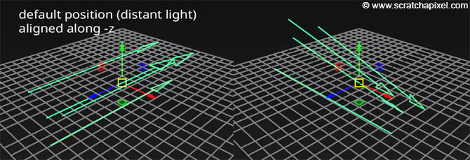
Similarly, for a distant light source, we assume by default that the light direction points along the negative z-axis (similar to the default orientation in Maya). In other words, the default light direction is (0,0,-1).
To modify or control the light direction, we adjust the light-to-world transformation matrix:
class DistantLight {
public:
    DistantLight(const Matrix44f &l2w, const Vec3f &c = Vec3f(1), const float &i = 1) : Light(l2w) {
        this->color = c;
        this->intensity = i;
        l2w.multDirMatrix(Vec3f(0, 0, -1), dir);
        dir.normalize();
    }
    Vec3f dir;
};
Now that we understand how to create lights in our system, let's explore simulating the appearance of diffuse objects.