Normals, Vertex Normals and Facing Ratio
Reading time: 11 mins.Now that we've reviewed the parameters that influence the appearance of objects (how bright they are, their color, etc.), we are ready to begin studying some basic shading techniques.
Normals
Normals play a central role in shading. It is well-known that an object appears brighter when oriented towards a light source. The orientation of an object's surface is crucial in determining the amount of light it reflects and thus its apparent brightness. This orientation at any point
-
The term "normal" (denoted by the capital letter
-
The brightness of a point on the surface of an object depends on the direction of the normal, which defines the orientation of the object's surface at that point with respect to the light. Another way to express this is to say that the brightness of the object at any given point on its surface depends on the angle between the normal at that point and the light direction.
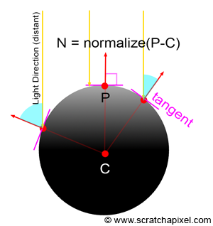
The question now is, how do we compute this normal? The complexity of the solution can vary greatly depending on the type of geometry being rendered. The normal of a sphere can generally be found easily. If we know the position of a point on the surface of a sphere and the sphere's center, the normal at this point can be computed by subtracting the point position from the sphere center:
Vec3f N = P - sphereCenter;
More complex techniques based on differential geometry can be used to compute the normal of a point on the surface of a sphere, but we won't study these techniques in this section.
If the object is a triangle mesh, then each triangle defines a plane, and the vector perpendicular to the plane is the normal for any point lying on the surface of that triangle. The vector perpendicular to the triangle plane can easily be obtained with the cross product of two edges of that triangle. Keep in mind that
Vec3f N = (v1-v0).crossProduct(v2-v0);
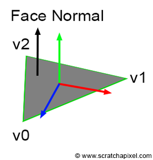
If the triangle lies in the xz plane, then the resulting normal should be
Computing the normal in this manner yields what we refer to as a face normal (because the normal is the same for the entire face, regardless of the point selected on that face or triangle). Normals for triangle meshes can also be defined at the vertices of the triangle, where they are known as vertex normals. Vertex normals are employed in a technique called smooth shading, which will be described at the end of this chapter. For the time being, we will focus only on face normals.
How and when you compute the surface normal at the point you are about to shade in your program does not matter. What is crucial is that you have this information available when you are ready to shade the point. In the few programs for this section where we executed some basic shading, we implemented a special method in every geometry class called getSurfaceProperties(). In this method, we computed the normal at the intersection point (in case ray-tracing is used) and other variables such as texture coordinates, which we will discuss later in this lesson. Here is what the implementation of these methods might look like for the sphere and triangle-mesh geometry types:
class Sphere : public Object
{
    ...
public:
    ...
    void getSurfaceProperties(
        const Vec3f &hitPoint,
        const Vec3f &viewDirection,
        const uint32_t &triIndex,
        const Vec2f &uv,
        Vec3f &hitNormal,
        Vec2f &hitTextureCoordinates) const
    {
        hitNormal = hitPoint - center;
        hitNormal.normalize();
        ...
    }
    ...
};

class TriangleMesh : public Object
{
    ...
public:
    void getSurfaceProperties(
        const Vec3f &hitPoint,
        const Vec3f &viewDirection,
        const uint32_t &triIndex,
        const Vec2f &uv,
        Vec3f &hitNormal,
        Vec2f &hitTextureCoordinates) const
    {
        const Vec3f &v0 = P[trisIndex[triIndex * 3]];
        const Vec3f &v1 = P[trisIndex[triIndex * 3 + 1]];
        const Vec3f &v2 = P[trisIndex[triIndex * 3 + 2]];
        hitNormal = (v1 - v0).crossProduct(v2 - v0);
        hitNormal.normalize();
        ...
    }
    ...
};
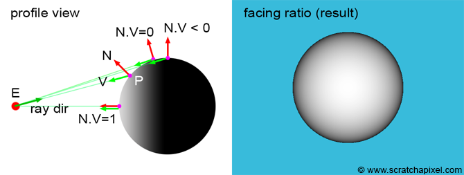
A Simple Shading Effect: Facing Ratio
Now that we know how to compute the normal of a point on the surface of an object, we have sufficient information to create a simple shading effect called the facing ratio. This technique involves computing the dot product of the normal at the point we want to shade and the viewing direction. Determining the viewing direction is straightforward. In ray tracing, it is simply the opposite of the direction of the ray that intersects the surface at point
Vec3f V = (E - P).normalize(); // or -ray.dir if you use ray tracing
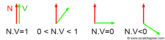
Remember, the dot product of two vectors returns 1 if the vectors are parallel and point in the same direction, and 0 if they are perpendicular. If the vectors point in opposite directions, the dot product is negative. Since we're not interested in negative values when using the result as a color, we need to clamp the result to zero:
float facingRatio = std::max(0.0f, N.dotProduct(V));
When the normal and the vector
Vec3f castRay(
    const Vec3f &orig, const Vec3f &dir,
    const std::vector<std::unique_ptr<Object>> &objects,
    const Options &options)
{
    Vec3f hitColor = options.backgroundColor;
    float tnear = kInfinity;
    Vec2f uv;
    uint32_t index = 0;
    Object *hitObject = nullptr;
    if (trace(orig, dir, objects, tnear, index, uv, &hitObject)) {
        Vec3f hitPoint = orig + dir * tnear;  // shaded point
        Vec3f hitNormal;
        Vec2f hitTexCoordinates;
        // Compute the normal at the point we want to shade
        hitObject->getSurfaceProperties(hitPoint, dir, index, uv, hitNormal, hitTexCoordinates);
        hitColor = std::max(0.f, hitNormal.dotProduct(-dir));  // facing ratio
    }

    return hitColor;
}
Congratulations! You have just learned about your first shading technique. Let's now explore a more realistic shading method that will simulate the effect of light on a diffuse object. But before we delve into this method, we first need to introduce and understand the concept of light.
Flat Shading vs. Smooth Shading and Vertex Normals
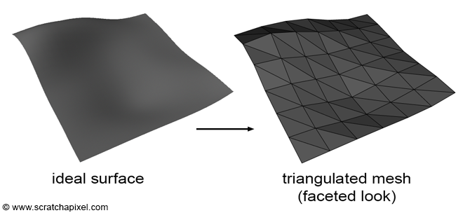
The limitation with triangle meshes is that they cannot perfectly represent smooth surfaces unless the triangles are very small. When applying the facing-ratio technique to a polygon mesh, you would need to compute the normal of the triangle intersected by the ray and calculate the facing ratio as the dot product between this face normal and the viewing direction. This approach results in the object having a faceted appearance, as depicted in the images below. This shading method is consequently known as flat shading.
As previously mentioned, the normal of a triangle can be found by computing the cross product of vectors, for example,
The technique of interpolating any primitive variables, including colors, texture coordinates, or normals using the triangle's barycentric coordinates has been reviewed in previous lessons. If you are not yet familiar with this method, we recommend reading the chapter The Rasterization Stage from the lesson "Rasterization: a Practical Implementation".
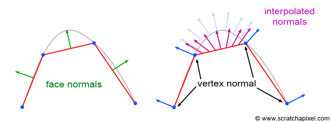
The image above illustrates the technique. Vertex normals, defined at the triangle's vertices, are oriented perpendicular to the smooth underlying surface that the triangle mesh approximates. Sometimes triangle meshes are not derived directly from a smooth surface, and vertex normals must be computed on the fly. While various techniques exist for computing vertex normals when no smooth surface is available, we won't explore them in this lesson. Instead, use software like Maya or Blender to manage this; for example, in Maya, you can select your polygon mesh and choose the "Soften Edge" option in the Normals menu.
From a practical and technical perspective, each triangle has its own set of three vertex normals, meaning the total number of vertex normals for a triangle mesh equals the number of triangles multiplied by three. In some instances, vertex normals on a vertex shared by two or more triangles are identical (they point in the same direction), but varying effects can be achieved by assigning them different orientations (e.g., to simulate hard edges on the surface).
Here is the source code for computing the interpolated normal at any point on the surface of a triangle, assuming you have the vertex normals for the triangle, the barycentric coordinates of this point, and the triangle index:
void getSurfaceProperties(
    const Vec3f &hitPoint,
    const Vec3f &viewDirection,
    const uint32_t &triIndex,
    const Vec2f &uv,
    Vec3f &hitNormal,
    Vec2f &hitTextureCoordinates) const
{
    const Vec3f &v0 = P[trisIndex[triIndex * 3]];
    const Vec3f &v1 = P[trisIndex[triIndex * 3 + 1]];
    const Vec3f &v2 = P[trisIndex[triIndex * 3 + 2]];
    hitNormal = (v1 - v0).crossProduct(v2 - v0);  // face normal

    // compute "smooth" normal using Gouraud's technique (interpolate vertex normals)
    const Vec3f &n0 = N[trisIndex[triIndex * 3]];
    const Vec3f &n1 = N[trisIndex[triIndex * 3 + 1]];
    const Vec3f &n2 = N[trisIndex[triIndex * 3 + 2]];
    hitNormal = (1 - uv.x - uv.y) * n0 + uv.x * n1 + uv.y * n2;
    hitNormal.normalize();  // normalize for safety, although N's are already normalized

    // texture coordinates
    const Vec2f &st0 = texCoordinates[trisIndex[triIndex * 3]];
    const Vec2f &st1 = texCoordinates[trisIndex[triIndex * 3 + 1]];
    const Vec2f &st2 = texCoordinates[trisIndex[triIndex * 3 + 2]];
    hitTextureCoordinates = (1 - uv.x - uv.y) * st0 + uv.x * st1 + uv.y * st2;
}
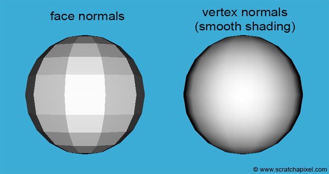
Although this technique produces the impression of a smooth surface, you can still notice the faceted silhouette of a polygon sphere, as shown in the image below. While the technique enhances the appearance of triangle meshes, it does not fully resolve the issue of their faceted look. The ultimate solutions are to use a subdivision surface, which will be discussed in a later section, or to increase the number of triangles used when converting smooth surfaces into triangle meshes.
Now, we are ready to learn how to reproduce the appearance of diffuse surfaces. However, diffuse surfaces require light to be visible. Thus, before we can study this technique, we first need to understand how light sources are handled in a 3D engine.