What Are Projection Matrices and Where/Why Are They Used?
Reading time: 14 mins.Heads Up Before You Dive In
Grasping the material in this lesson requires prior knowledge in several key areas. Make sure you're comfortable with matrices, the process of transforming points between different spaces, understanding perspective projection (including the calculation of 3D point coordinates on a canvas), and the fundamentals of the rasterization algorithm. If any of these topics sound unfamiliar or you need a refresher, we strongly recommend revisiting the preceding lessons and the dedicated Geometry lesson. This foundational understanding will equip you with the necessary tools to fully engage with and benefit from the upcoming content.
Exploring Projection Matrices
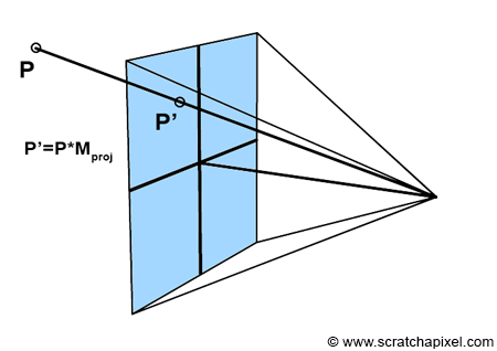
Projection matrices are specialized 4x4 matrices designed to transform a 3D point in camera space into its projected counterpart on the canvas. Essentially, when you multiply a 3D point by a projection matrix, you determine its 2D coordinates on the canvas within NDC (Normalized Device Coordinates) space. Recall from earlier discussions that points in NDC space fall within the range [-1, 1], adhering to the conventions of graphics APIs like Direct3D or OpenGL.
Projection matrices adhere to two NDC space conventions: either the coordinates fall within the range [-1, 1], common to most real-time graphics APIs like OpenGL or Direct3D, or within [0, 1], as specified by RenderMan. Here, we will focus on the [-1, 1] range, prevalent in real-time 3D APIs.
In simpler terms, the act of multiplying a 3D point by a projection matrix achieves what previously required a series of operations, including the perspective divide and remapping from screen space to NDC space. This complex process:
// Convert to screen space
Vec2f P_screen;
P_screen.x = near * P_camera.x / -P_camera.z;
P_screen.y = near * P_camera.y / -P_camera.z;

// Convert point from screen space to NDC space (range [-1, 1])
Vec3f P_ndc;
P_ndc.x = 2 * P_screen.x / (r - l) - (r + l) / (r - l);
P_ndc.y = 2 * P_screen.y / (t - b) - (t + b) / (t - b);
Can now be streamlined into a single point-matrix multiplication, given a projection matrix \(M_{proj}\):
Vec3f P_ndc;
M_proj.multVecMatrix(P_camera, P_ndc);
This approach consolidates the previously separate variables—\(near\), \(t\), \(b\), \(l\), and \(r\)—representing the near clipping plane and the screen's boundaries, into a concise matrix operation. This lesson's goal is to demystify \(M_{proj}\), elucidating its construction and how it encapsulates:
-
The perspective division,
-
The remapping from screen space to NDC space.
We'll delve into how this matrix incorporates various transformation steps, including the near clipping plane and screen dimensions.
It's crucial to remember that projection matrices are intended for transforming vertices or 3D points, not vectors. Their primary purpose is to project 3D objects' vertices onto the screen, adhering to perspective rules, creating images of these objects. As discussed in the geometry lesson, a point can also be regarded as a matrix—a [1x3] row vector matrix in row-major order, as utilized on Scratchapixel. For matrix multiplication to occur, the number of columns in the left matrix must match the number of rows in the right matrix. This requirement implies that multiplying a 3D point ([1x3]) by a 4x4 matrix directly is not feasible.
The workaround involves treating points as [1x4] vectors, enabling their multiplication by a 4x4 matrix. The result is another [1x4] matrix, or 4D points with homogeneous coordinates. These coordinates are only directly applicable as 3D points if their fourth component is 1, allowing the first three components to represent a standard 3D Cartesian point. The transition from Homogeneous to Cartesian coordinates, particularly when involving projection matrices, will be discussed in the following chapter. Homogeneous coordinates are generally only considered when dealing with projection matrices, necessitating explicit handling of the fourth coordinate, unlike with standard transformation matrices where it's implicitly managed.
The commonly referred "conventional" 4x4 transformation matrices are part of affine transformations in mathematics, while projection matrices fall under projective transformations. Both types require homogeneous coordinates for point multiplication, a topic expanded upon in the next chapter and the geometry lesson.
This differentiation means that 4D points and, by extension, homogeneous coordinates, are primarily encountered in rendering contexts involving projection matrices. Other times, the explicit handling of these coordinates is unnecessary. However, projection matrices introduce complexity due to the clipping process—a critical rendering step—occurring during the point's transformation by the projection matrix. This intermediate process, discussed in subsequent chapters, is often conflated with projection matrices in literature without clear explanation, adding to the confusion. This lesson aims to clarify the function and application of projection matrices, separating them from the intertwined clipping process.
Understanding Their Application and Significance
Projection matrices are widely discussed across this site and various specialized forums, yet they remain a source of confusion for many. Their widespread discussion hints at their importance, even though they are often found to be inadequately explained. This lack of comprehensive documentation is puzzling, given the critical role these matrices play. They are integral to the functionality of real-time graphics APIs like OpenGL, Direct3D, WebGL, Vulkan, Metal, and WebGPU, which enjoy widespread use in video gaming and general desktop graphics applications. These APIs serve as a bridge between the software you develop and the graphics processing unit (GPU). It's worth noting, as previously mentioned, that GPUs are designed to execute the rasterization algorithm. Historically, in what's known as the fixed function pipeline, GPUs would utilize a projection matrix to map points from camera space to normalized device coordinates (NDC). However, the GPU itself lacked the capability to construct this matrix, placing the onus on developers to do so.
// This code is outdated and should not be used. OpenGL, along
// with DirectX, was previously favored for real-time graphics.
glMatrixMode(GL_PROJECTION);
glLoadIdentity();
glFrustum(l, r, b, t, n, f);  // Defines the matrix with screen dimensions and clipping distances
glMatrixMode(GL_MODELVIEW);
glLoadIdentity();
glTranslate(0, 0, 10);
// Additional code omitted for brevity
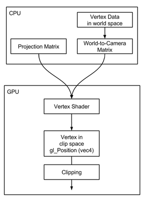
However, this code is now obsolete and provided only for context and to understand the evolution of graphics programming. Modern practices have moved away from such direct use of OpenGL, as these features have been deprecated and OpenGL's prevalence has declined. In contrast, the contemporary "programmable" rendering pipeline—found in DirectX, Vulkan, Metal, and newer versions of OpenGL—employs projection matrices differently. Rather than directly mapping points from camera to NDC space, they now transform points to an intermediary "clip space." While the details of clip space can be complex, it's enough to understand that it involves points represented in homogeneous coordinates, a concept referring to the 4-dimensional points discussed previously.
In the contemporary GPU rendering process within the programmable pipeline, transforming vertices through projection matrix multiplication is carried out in the vertex shader. Essentially, a vertex shader is a concise program designed to convert the vertices of 3D objects from camera space to clip space. It operates by accepting a vertex and a projection matrix (both associated with the shader) and then computes the product of the vertex and the projection matrix. This product is assigned to a predefined global variable, gl_Position, within OpenGL, signifying the transformed vertex location in clip space. It's important to note that both gl_Position and the input vertex are defined as vec4, meaning they are treated as points with homogeneous coordinates. Here's a simplified example of how a vertex shader might look:
uniform mat4 projMatrix; // Projection matrix
in vec3 position; // Vertex position

void main()
{
    gl_Position = projMatrix * vec4(position, 1.0); // Transform to clip space
}
The execution of this vertex shader by the GPU is a key step in processing each vertex within the scene. When using graphics APIs like OpenGL or Direct3D, the vertex information and how these vertices interconnect to form the geometry of meshes are stored in the GPU's memory. The GPU then transforms this vertex data from its initial space to clip space. The initial space of these vertices at the time of processing by the vertex shader is determined by how you prepare them:
-
You may opt to pre-transform the vertices from world space to camera space before uploading them to the GPU's memory. This approach ensures that vertices are already in camera space when processed by the vertex shader.
-
Alternatively, you can upload the vertices in world space to the GPU's memory. In this case, alongside the projection matrix (commonly denoted as P or Proj), the shader also needs the world-to-camera transformation matrix (often labeled M or MV, where MV stands for "model-view" matrix, indicating a combination of the object-to-world and world-to-camera transformations). Object space refers to the original position of an object before any transformation, while world space is the coordinate system after applying an object-to-world matrix. To properly transform vertices in this scenario, they must first be converted from world to camera space, followed by the projection matrix application. If vertices are in world space upon entering the vertex shader, only the view component (the world-to-camera matrix) is required. The process could be represented in pseudocode as follows:
uniform mat4 P;  // Projection matrix
uniform mat4 MV; // Model-view matrix (object-to-world * world-to-camera)

in vec3 position; // Vertex position

void main()
{
    gl_Position = P * MV * vec4(position, 1.0); // Transform to clip space
}
P.S.: Did you observe an interesting detail? In GLSL shaders, like the one mentioned above, the point is positioned to the right of the matrix. This arrangement, known from geometry lessons, is referred to as post-multiplication. It hints at the convention used in this and other real-time graphics APIs, such as OpenGL and now Vulkan, where matrices are structured in a column-major order. Quite an insightful observation!
Many developers have a preference for the latter method, and there are practical reasons behind this choice. While it's possible to combine the world-to-camera matrix with the projection matrix into a single matrix, it's generally advisable to pass them as two distinct matrices to the vertex shader for reasons beyond the scope of this discussion.
uniform mat4 PMV;  // Combined projection and model-view matrix

in vec3 position;

void main()
{
    gl_Position = PMV * vec4(position, 1.0); // Transform vertex position
}

int main(...)
{
    ...
    // Assuming the use of row-vector matrices
    Matrix44f projectionMatrix(...);
    Matrix44f modelViewMatrix(...);
    Matrix44f PM = modelViewMatrix * projectionMatrix;
    // OpenGL expects column-vector matrices, necessitating a matrix transpose
    PM.transpose();
    // Retrieve the shader variable location for 'PM'
    GLint loc = glGetUniformLocation(p, "PM");
    // Update the shader variable with our combined matrix
    glUniformMatrix4fv(loc, 1, false, &PM.m[0][0]);
    ...
    render();
    ...
    return 0;
}
If you're not well-versed in graphics API usage, or if your experience is more with Direct3D than OpenGL, don't fret. The underlying principles are consistent across both, allowing for easy identification of parallels. The essence of the code is to configure the projection and model-view matrices (merging object-to-world and world-to-camera transformations) and to combine these matrices. This approach simplifies the process, requiring only a single matrix to be passed to the vertex shader. In OpenGL, identifying the shader variable's location necessitates using the glGetUniformLocation() function.
The specifics of how glGetUniformLocation() functions may not be crucial for all readers, but in brief, it searches for a shader program variable by name and returns its location. This location is subsequently used with glUniform() calls to set the shader variable. In the context of OpenGL or Direct3D, a "program" comprises both a vertex and a fragment shader, which together determine the transformation of model vertices to clip space (vertex shader's role) and the rendering of the object's appearance (fragment shader's task).
After locating the shader variable with glGetUniformLocation(), we use glUniformMatrix4fv() to set its value. During rendering, the vertex shader processes each vertex, converting them from object space to clip space. This transformation involves multiplying the vertex's position, which is initially in object space, by the PM matrix. The PM matrix is a composite of the projection and model-view matrices, integrating their effects. This step is pivotal in the GPU rendering process for accurately rendering objects.
Although this discussion does not serve as an in-depth introduction to the GPU rendering pipeline, the goal is to provide a sufficient understanding of the concept. It's important to note that, as of 2024, the focus should be on utilizing programmable pipelines, which still necessitate the creation of projection matrices by the programmer. This requirement underscores the significance of projection matrices and explains their popularity in computer graphics discussions. However, in the modern rendering pipeline, employing a projection matrix is not strictly necessary. The essential task is to transform vertices to clip space, which can be achieved either through a matrix or equivalent code. For instance:
uniform float near, b, t, l, r; // Near clip plane and screen coordinates

in vec3 position;

void main()
{
    // Equivalent operations to using a projection matrix
    gl_Position.x = ...; // Custom transformation code
    gl_Position.y = ...; // Custom transformation code
    gl_Position.z = ...; // Custom transformation code
    gl_Position.w = ...; // Custom transformation code
}
This flexibility in the programmable pipeline allows for alternative methods of vertex transformation, offering greater control over the process. While most scenarios will likely use standard projection techniques, understanding how to construct a projection matrix remains essential for those opting to directly manipulate vertex positions through custom code.
Key takeaways from this section include:
-
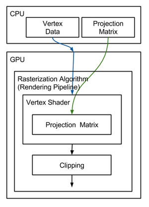
The GPU rendering pipeline fundamentally relies on the rasterization algorithm, where projection matrices are instrumental in transitioning vertices from camera space to clip space. Given the prevalence of GPUs and the central role of projection matrices in image generation, they are a focal point of interest in the field.
-
In the programmable pipeline, the vertex shader is responsible for moving vertices into clip space, with the projection matrix typically being a shader variable. This matrix is defined on the CPU before shader execution. Understanding how to construct this matrix and grasp the concept of clip space is crucial for effective graphics programming.
Orthographic vs. Perspective Projection Matrix

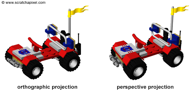
To wrap up this chapter, you might be curious about the title "The Perspective and Orthographic Projection Matrix" and the differences between these two types of projection matrices. Fundamentally, both serve the purpose of projecting 3D points onto a 2D plane. We've already delved into perspective projection, where as the viewing angle narrows (theoretically approaching zero), the sides of the frustum's pyramid become parallel. In such a scenario, objects maintain consistent size in the rendered image regardless of their distance from the camera, a characteristic known as orthographic projection. Despite orthographic projection appearing less natural compared to perspective projection, it finds its utility in certain contexts. A notable example is the game Sim City, which utilizes orthographic projection to achieve its distinctive visual style.
Projection Matrix in Ray-Tracing
It's important to reiterate that in ray tracing, the concept of projecting points onto a screen is not applicable. Instead, the technique involves casting rays from the image plane and detecting their intersections with scene objects, bypassing the need for projection matrices.
Looking Forward
Beginning with the basics of constructing a simple projection matrix is an effective approach to understanding the broader concepts discussed here. Familiarity with homogeneous coordinates paves the way to grasp further concepts like clipping, which are intricately linked to projection matrices. The initial perspective projection matrix we'll explore in Chapter Three may not exhibit the complexity of those utilized in OpenGL or Direct3D, but it will serve to elucidate the fundamental workings of projection matrices — specifically, their role in transforming vertices from any given space to clip space. For the ensuing two chapters, our focus will revert to the foundational aspect of projection matrices: their function in transitioning points from camera space to NDC space. The transition to discussing the transformation of points to clip space will be reserved for Chapter Four, where we'll dissect the intricacies of the OpenGL matrix. For now, it's sufficient to understand that projection matrices are instrumental in converting vertices from camera space to NDC space, bearing in mind that this definition is provisional.