Perspective Correct Interpolation and Vertex Attributes
Reading time: 18 mins.Interpolating Vertex Attributes
As mentioned in the previous chapter, barycentric coordinates can be used to interpolate any variables at the triangle vertex positions. So far, we have used them to find the z-coordinate of the point on the 2D triangle that projects to the pixel center. However, as we just said, we could, in principle, use them to interpolate any other variable—be it the triangle vertices themselves, colors, normals, or texture coordinates, which are essential for texturing.
Calculating the color of the point on the 3D triangle that projects to the pixel center, its normal, or its texture coordinates is required if you want to later shade that point, which generally involves determining its color (and opacity). This color is a combination of its intrinsic base color and the point's orientation, defined by its normal, which determines how much light from the environment it reflects back to the camera. Note that the color of the point can either be a constant color or come from a texture, in which case being able to properly interpolate texture coordinates is essential. This process is explained in the lesson on texturing. Data attached to the triangle vertices are generally called primitive variables or vertex attributes.
Vertex shading is a technique that consists of only rendering the shading at the triangle vertex locations. For instance, one might calculate the result of the lighting at the triangle vertex positions, store them alongside the vertices, and then evaluate any point on the triangle surface during the shading stage by interpolating these calculations. While this method isn't used much anymore, it was notably popular in the 1990s and early 2000s in video games, as it required fewer calculations, thereby saving computational resources to achieve real-time performance.
Now, there is a problem, and that's why this chapter exists. The problem is that, like with the interpolation of the point's z-coordinate, interpolating the raw primitive variable using just the points' barycentric coordinates doesn't work. It's a problem very similar to the one described in the previous chapter, but don't worry—we are about to explain the issue in detail and, as usual, present a solution. The solution to this problem is known as perspective-correct interpolation, and this is what we will study now. One might question why we address this topic here rather than in the shading section, given its closer relation to shading. While vertex attributes are indeed more directly related to shading, the discussion on perspective-correct interpolation is particularly relevant to rasterization.
Perspective Correct Vertex Attribute Interpolation
As you know, we store the z-coordinates of the original vertices (from camera space) in the z-coordinate of our projected vertices (in screen space). This step is crucial for calculating the depth of points across the surface of the projected triangle, which is essential for resolving the visibility problem. Depth calculation involves linearly interpolating the reciprocal of the z-coordinates of the triangle vertices using barycentric coordinates. This interpolation technique can also be applied to any variable defined at the triangle's vertices, similar to how we store the original z-coordinates in the projected points. Commonly, triangles' vertices may carry a color. The other two prevalent attributes stored at the vertices are texture coordinates and normals. Texture coordinates, which are 2D coordinates used for texturing, and normals, which indicate the surface orientation, are vital for texturing and shading, respectively. This lesson will specifically focus on color and texture coordinates to illustrate the concept of perspective-correct interpolation, but the same technique will apply to any vertex attribute (or primitive variable).
As discussed in the chapter on rasterization, colors or other attributes can be specified for the triangle vertices. These attributes can be interpolated across the surface of the triangle using barycentric coordinates to determine their values at any point within the triangle. In essence, vertex attributes must be interpolated across the surface of a triangle during rasterization. The process is as follows:
-
Assign multiple vertex attributes to the triangle's vertices as desired. These attributes are defined on the original 3D triangle in camera space. For illustration, we will assign two vertex attributes: one for color and one for texture coordinates.
-
Project the triangle onto the screen, converting the triangle's vertices from camera space to raster space.
-
In screen space, rasterize the triangle. Compute the barycentric coordinates of a pixel sample if it is contained within the triangle's edges.
-
Interpolate the colors (or texture coordinates) defined at the triangle's vertices using the computed barycentric coordinates with the formula:
$$C_P = \lambda_0 \cdot C_0 + \lambda_1 \cdot C_1 + \lambda_2 \cdot C_2$$Here, \(\lambda_0\), \(\lambda_1\), and \(\lambda_2\) represent the pixel's barycentric coordinates, and \(C_0\), \(C_1\), and \(C_2\) are the colors at the triangle vertices. The resulting \(C_P\) is then assigned to the current pixel in the framebuffer. Similarly, this method can compute the texture coordinates of the point on the triangle that the pixel overlaps:
$$ST_P = \lambda_0 \cdot ST_0 + \lambda_1 \cdot ST_1 + \lambda_2 \cdot ST_2$$These coordinates are used for texturing (refer to the lesson on Texture Mapping in this section to learn more about texture coordinates and texturing).
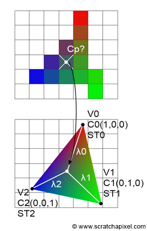
However, both interpolating the color and the texture coordinates this way won't work. To understand why, let's examine what happens to a point located in the middle of a 3D quad. As depicted in the top view of Figure 2, we have a quad, and point \(P\) is clearly in the middle of that quad (i.e., \(P\) is located at the intersection of the quad's diagonals). However, when we view this quad from a different viewpoint, it becomes evident that, depending on the quad's orientation relative to the camera, \(P\) no longer appears to be at the center of the quad. This discrepancy is due to perspective projection, which, as mentioned previously, preserves lines but does not preserve distances.
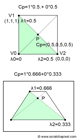
It's important to remember that barycentric coordinates are computed in screen space. Suppose the quad consists of two triangles. In 3D space, \(P\) is equidistant from \(V1\) and \(V2\), giving it barycentric coordinates in 3D space of \(\{0, 0.5, 0.5\}\). Yet, in screen space, since \(P\) is closer to \(V1\) than to \(V2\), \(\lambda_1\) is greater than \(\lambda_2\) (with \(\lambda_0\) equal to 0).
Here’s the problem: If \(V1\) is white and \(V2\) is black, then the color at \(P\) should be 0.5. However, if \(\lambda_1\) is greater than \(\lambda_2\), the interpolated value will be greater than 0.5. This clearly indicates a problem with our interpolation technique. Assuming, as in Figure 1, that \(\lambda_1\) and \(\lambda_2\) are 0.666 and 0.334 respectively, interpolating the triangle's vertex colors yields:
$$C_P = \lambda_0 \cdot C_0 + \lambda_1 \cdot C_1 + \lambda_2 \cdot C_2 = 0 \cdot C_0 + 0.666 \cdot 1 + 0.334 \cdot 0 = 0.666.$$This results in a value of 0.666 for \(P\), not the expected 0.5. Doesn't this problem closely resemble the issue we encountered in the previous chapter when interpolating the vertex's z-coordinates? Fortunately, finding the correct way to properly interpolate primitive variables is just as straightforward.

Interpolating Vertex Attributes
Imagine we have a triangle with z-coordinates \(Z_0\) and \(Z_1\) on each side, as shown in Figure 3. By connecting these two points, we can interpolate the z-coordinate of a point on this line using linear interpolation. Similarly, we can interpolate between two vertex attribute values, \(C_0\) and \(C_1\), defined at the same positions on the triangle as \(Z_0\) and \(Z_1\), respectively. Since both \(Z\) and \(C\) are computed using linear interpolation, we can establish the following equality (Equation 1):
$$\frac{Z - Z_0}{Z_1 - Z_0} = \dfrac{C - C_0}{C_1 - C_0}.$$Recalling from the last chapter (Equation 2):
$$Z = \dfrac{1}{\dfrac{1}{Z_0}(1-q) + \dfrac{1}{Z_1}q}.$$First, we substitute the equation for \(Z\) (Equation 2) into the left-hand side of Equation 1. The trick to simplifying the resulting equation involves multiplying the numerator and denominator of Equation 2 by \(Z_0Z_1\) to eliminate the \(1/Z_0\) and \(1/Z_1\) terms (don't worry, we will remove that \(Z_0Z_1\) term at the end):
$$ \begin{align*} \dfrac{\dfrac{1}{\dfrac{1}{Z_0}(1-q)+\dfrac{1}{Z_1}q} - Z_0}{Z_1 - Z_0} & = \dfrac{\dfrac{Z_0Z_1}{Z_1(1-q)+Z_0q} - Z_0}{Z_1 - Z_0}\\ & = \dfrac{\dfrac{Z_0Z_1 - Z_0(Z_1(1-q) + Z_0q)}{Z_1(1-q) + Z_0q}}{Z_1 - Z_0}\\ & = \dfrac{\dfrac{Z_0Z_1q - Z_0^2q}{Z_1(1-q) + Z_0q}}{Z_1 - Z_0}\\ & = \dfrac{\dfrac{Z_0q(Z_1 - Z_0)}{Z_1(1-q) + Z_0q}}{Z_1 - Z_0}\\ & = \dfrac{Z_0q}{Z_1(1-q) + Z_0q}\\ & = \dfrac{Z_0q}{q(Z_0 - Z_1) + Z_1}. \end{align*} $$Solving for \(C\) now:
$$ \dfrac{C - C_0}{C_1 - C_0} = \dfrac{Z_0 q}{q(Z_0 - Z_1) + Z_1} $$Cross-multiply to eliminate the fractions:
$$ (C - C_0) \cdot \left[q(Z_0 - Z_1) + Z_1\right] = (C_1 - C_0) \cdot Z_0 q $$Now, expand both sides:
$$ C \cdot \left[q(Z_0 - Z_1) + Z_1\right] - C_0 \cdot \left[q(Z_0 - Z_1) + Z_1\right] = C_1 \cdot Z_0 q - C_0 \cdot Z_0 q $$Now, we want to isolate \(C\) on one side of the equation. So, move all the terms involving \(C\) to one side:
$$ C \cdot \left[q(Z_0 - Z_1) + Z_1\right] = C_1 \cdot Z_0 q - C_0 \cdot \left[q(Z_0 - Z_1) + Z_1\right] + C_0 \cdot Z_0 q $$Factor out the common terms and solve for \(C\):
$$ C = \dfrac{C_1 \cdot Z_0 q + C_0 \cdot Z_1 (1 - q)}{q(Z_0 - Z_1) + Z_1} $$Remember that we multiplied the numerator and denominator of Equation 2 by \(Z_0Z_1\), so we need to remove this term now, which we do by multiplying the numerator and the denominator by \(1/Z_0Z_1\). The numerator becomes:
$$ \dfrac{1}{Z_0 Z_1} \cdot \left(C_1 \cdot Z_0 q + C_0 \cdot Z_1 (1 - q)\right) $$This simplifies to:
$$ \dfrac{C_1 \cdot q}{Z_1} + \dfrac{C_0 \cdot (1 - q)}{Z_0} $$The denominator becomes:
$$ \dfrac{1}{Z_0 Z_1} \cdot \left(q(Z_0 - Z_1) + Z_1\right) $$Expanding this gives:
$$ \dfrac{q}{Z_1} - \dfrac{q}{Z_0} + \dfrac{1}{Z_0} $$Simplifying, this is:
$$ \dfrac{1 - q}{Z_0} + \dfrac{q}{Z_1} $$So, the final expression for \(C\) after multiplying both the numerator and denominator by \(\dfrac{1}{Z_0 Z_1}\) is:
$$ C = \dfrac{\dfrac{C_1 \cdot q}{Z_1} + \dfrac{C_0 \cdot (1 - q)}{Z_0}}{\dfrac{1 - q}{Z_0} + \dfrac{q}{Z_1}} $$Remember that:
$$ Z = \dfrac{1}{\dfrac{1 - q}{Z_0} + \dfrac{q}{Z_1}} $$And so:
$$ C = Z \left[ \dfrac{C_0}{Z_0}(1-q) + \dfrac{C_1}{Z_1}q \right]. $$This is the final form of the equation, showing how \(C\) is interpolated in a perspective-correct way.
As you may have guessed if you've been reading through the previous chapter—and it's so important that we repeat this here—this is what's referred to in mathematics as rational-linear or hyperbolic interpolation. I've explained what this means in the previous chapter, so I won't repeat that content here, but if you haven't read it yet, I strongly recommend you do so. The term perspective-correct interpolation is an application of rational-linear or hyperbolic interpolation. Instead of directly interpolating attributes like depth, color, or texture coordinates in screen space, you first interpolate the attributes divided by the depth (or the reciprocal of the z-coordinate, \( \frac{1}{z} \)).
1. Interpolate the ratio: You interpolate the attribute values divided by the depth (e.g., \( \frac{C_0}{Z_0} \) and \( \frac{C_1}{Z_1} \)) using the appropriate barycentric coordinates or interpolation factor.
2. Multiply the result by z: After obtaining the interpolated value of the ratio, you then multiply it by the depth (or z-coordinate) of the pixel in question to obtain the final interpolated attribute value.
In formula terms, if \( C_0 \) and \( C_1 \) are attribute values at two vertices, and \( Z_0 \) and \( Z_1 \) are their corresponding depths, the perspective-correct interpolation formula is:
$$ C = Z \left[ \frac{C_0}{Z_0}(1 - q) + \frac{C_1}{Z_1}q \right] $$Here, \( q \) is the interpolation factor or barycentric coordinate, and \( Z \) is the interpolated depth.
So, you first interpolate the ratio and then multiply the result by z. This ensures that the interpolation accounts for perspective distortion, leading to more accurate rendering of textures, colors, and other attributes on 3D surfaces.
This result is fundamental to rasterization and is what you need to use to interpolate vertex attributes correctly.
Here is an updated version of the code from Chapter Three, illustrating perspective-correct vertex attribute interpolation:
To compile, use:
-
For naive vertex attribute interpolation:
c++ -o raster3d raster3d.cpp -
For perspective-correct interpolation:
c++ -o raster3d raster3d.cpp -D PERSP_CORRECT
// (c) www.scratchapixel.com

#include <cstdio>
#include <cstdlib>
#include <fstream>

typedef float Vec2[2];
typedef float Vec3[3];
typedef unsigned char Rgb[3];

inline
float edgeFunction(const Vec3 &a, const Vec3 &b, const Vec3 &c) {
    return (c[0] - a[0]) * (b[1] - a[1]) - (c[1] - a[1]) * (b[0] - a[0]);
}

int main(int argc, char **argv) {
    Vec3 v2 = {-48, -10, 82};
    Vec3 v1 = {29, -15, 44};
    Vec3 v0 = {13, 34, 114};
    Vec3 c2 = {1, 0, 0};
    Vec3 c1 = {0, 1, 0};
    Vec3 c0 = {0, 0, 1};

    const uint32_t w = 512;
    const uint32_t h = 512;

    // Project triangle onto the screen
    v0[0] /= v0[2], v0[1] /= v0[2];
    v1[0] /= v1[2], v1[1] /= v1[2];
    v2[0] /= v2[2], v2[1] /= v2[2];
    // Convert from screen space to NDC then raster (in one go)
    v0[0] = (1 + v0[0]) * 0.5 * w, v0[1] = (1 + v0[1]) * 0.5 * h;
    v1[0] = (1 + v1[0]) * 0.5 * w, v1[1] = (1 + v1[1]) * 0.5 * h;
    v2[0] = (1 + v2[0]) * 0.5 * w, v2[1] = (1 + v2[1]) * 0.5 * h;

#ifdef PERSP_CORRECT
    // Divide vertex-attribute by the vertex z-coordinate
    c0[0] /= v0[2], c0[1] /= v0[2], c0[2] /= v0[2];
    c1[0] /= v1[2], c1[1] /= v1[2], c1[2] /= v1[2];
    c2[0] /= v2[2], c2[1] /= v2[2], c2[2] /= v2[2];
    // Pre-compute 1 over z
    v0[2] = 1 / v0[2], v1[2] = 1 / v1[2], v2[2] = 1 / v2[2];
#endif

    Rgb *framebuffer = new Rgb[w * h];
    memset(framebuffer, 0, w * h * 3);

    float area = edgeFunction(v0, v1, v2);

    for (uint32_t j = 0; j < h; ++j) {
        for (uint32_t i = 0; i < w; ++i) {
            Vec3 p = {i + 0.5, h - j + 0.5, 0};
            float w0 = edgeFunction(v1, v2, p);
            float w1 = edgeFunction(v2, v0, p);
            float w2 = edgeFunction(v0, v1, p);
            if (w0 >= 0 && w1 >= 0 && w2 >= 0) {
                w0 /= area, w1 /= area, w2 /= area;
                float r = w0 * c0[0] + w1 * c1[0] + w2 * c2[0];
                float g = w0 * c0[1] + w1 * c1[1] + w2 * c2[1];
                float b = w0 * c0[2] + w1 * c1[2] + w2 * c2[2];
#ifdef PERSP_CORRECT
                float z = 1 / (w0 * v0[2] + w1 * v1[2] + w2 * v2[2]);
                // Multiply the result by z for perspective-correct interpolation
                r *= z, g *= z, b *= z;
#endif
                framebuffer[j * w + i][0] = static_cast<unsigned char>(r * 255);
                framebuffer[j * w + i][1] = static_cast<unsigned char>(g * 255);
                framebuffer[j * w + i][2] = static_cast<unsigned char>(b * 255);
            }
        }
    }

    std::ofstream ofs;
    ofs.open("./raster2d.ppm");
    ofs << "P6\n" << w << " " << h << "\n255\n";
    ofs.write(reinterpret_cast<char*>(framebuffer), w * h * 3);
    ofs.close();

    delete[] framebuffer;

    return 0;
}
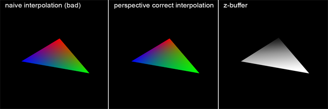
Computing the sample depth requires the use of the reciprocal of the vertex's z-coordinates. For this reason, we pre-compute these values before looping over all pixels. If perspective correct interpolation is chosen, the vertex attribute values are divided by the z-coordinate of the vertex they are associated with. The following image illustrates, on the left, an image computed without perspective correct interpolation, in the middle, an image with perspective correct interpolation, and on the right, the content of the z-buffer (displayed as a grayscale image where objects closer to the screen appear brighter). Although the difference is subtle, in the left image, each color seems to roughly fill the same area, due to colors being interpolated within the "space" of the 2D triangle (as if the triangle were a flat surface parallel to the screen). However, examining the triangle vertices (and the depth buffer) reveals that the triangle is not parallel to the screen but is oriented at a certain angle. Because the vertex painted in green is closer to the camera than the other two, this part of the triangle occupies a larger part of the screen, as visible in the middle image (the green area is larger than the blue or red areas). The middle image shows correct interpolation, akin to what would be achieved using a graphics API such as OpenGL, Vulkan, Metal or Direct3D.
The distinction between correct and incorrect perspective interpolation becomes even more apparent when applied to texturing. In the next example, texture coordinates were assigned to the triangle vertices as vertex attributes, and these coordinates were used to generate a checkerboard pattern on the triangle. The task of rendering the triangle with or without perspective correct interpolation is left as an exercise. The image below demonstrates the result, which also aligns with an image of the same triangle featuring the same pattern rendered in Maya. This outcome suggests our code is performing as intended. Similar to color interpolation, all vertex attributes, including texture coordinates (often denoted as ST coordinates), require division by the z-coordinate of the vertex they are associated with. Later in the code, the interpolated texture coordinate value is multiplied by Z. Here are the modifications made to the code:
// (c) www.scratchapixel.com

#include <cstdio>
#include <cstdlib>
#include <fstream>
#include <cmath> // For fmod function

typedef float Vec2[2];
typedef float Vec3[3];
typedef unsigned char Rgb[3];

inline
float edgeFunction(const Vec3 &a, const Vec3 &b, const Vec3 &c) {
    return (c[0] - a[0]) * (b[1] - a[1]) - (c[1] - a[1]) * (b[0] - a[0]);
}

int main(int argc, char **argv) {
    Vec3 v2 = {-48, -10, 82};
    Vec3 v1 = {29, -15, 44};
    Vec3 v0 = {13, 34, 114};
	...
    // Texture coordinates
    Vec2 st2 = {0, 0};
    Vec2 st1 = {1, 0};
    Vec2 st0 = {0, 1};
	...
#ifdef PERSP_CORRECT
    // Divide vertex attributes by the vertex's z-coordinate
    c0[0] /= v0[2], c0[1] /= v0[2], c0[2] /= v0[2];
    c1[0] /= v1[2], c1[1] /= v1[2], c1[2] /= v1[2];
    c2[0] /= v2[2], c2[1] /= v2[2], c2[2] /= v2[2];

    st0[0] /= v0[2], st0[1] /= v0[2];
    st1[0] /= v1[2], st1[1] /= v1[2];
    st2[0] /= v2[2], st2[1] /= v2[2];

    // Pre-compute the reciprocal of z
    v0[2] = 1 / v0[2], v1[2] = 1 / v1[2], v2[2] = 1 / v2[2];
#endif

    for (uint32_t j = 0; j < h; ++j) {
        for (uint32_t i = 0; i < w; ++i) {
            if (w0 >= 0 && w1 >= 0 && w2 >= 0) {
                float s = w0 * st0[0] + w1 * st1[0] + w2 * st2[0];
                float t = w0 * st0[1] + w1 * st1[1] + w2 * st2[1];
#ifdef PERSP_CORRECT
                // Calculate the depth of the point on the 3D triangle that the pixel overlaps
                float z = 1 / (w0 * v0[2] + w1 * v1[2] + w2 * v2[2]);
                // Multiply the interpolated result by z for perspective-correct interpolation
                s *= z, t *= z;
#endif
                // Create a checkerboard pattern
                float pattern = (fmod(s * M, 1.0) > 0.5) ^ (fmod(t * M, 1.0) < 0.5);
                framebuffer[j * w + i][0] = (unsigned char)(pattern * 255);
                framebuffer[j * w + i][1] = (unsigned char)(pattern * 255);
                framebuffer[j * w + i][2] = (unsigned char)(pattern * 255);
            }
        }
    }

    return 0;
}
Here is the result you should expect:

What's Next?
In the final chapter of this lesson, we will discuss ways to enhance the rasterization algorithm. Although we won't delve into implementing these techniques specifically, we will explain how the final code works and how these improvements could theoretically be integrated.