The Projection Stage
Reading time: 14 mins.Quick Review
In the previous chapter, we provided a high-level overview of the rasterization rendering technique. This technique can be broken down into two main stages: first, projecting the vertices of the triangle onto the canvas, and then rasterizing the triangle itself. Rasterization, in this context, means "breaking apart" the triangle's shape into pixels or raster element squares—the latter term being how pixels were referred to in the past. In this chapter, we will revisit the first step. We have already discussed this method in the two previous lessons; therefore, we will not explain it here again. If you have any doubts about the principles behind perspective projection, we recommend revisiting those lessons. However, in this chapter, we will explore a few new techniques related to projection that will be valuable when we discuss the perspective projection matrix. We will introduce a new method for remapping the coordinates of the projected vertices from screen space to NDC (Normalized Device Coordinates) space. Additionally, we will delve deeper into the role of the z-coordinate in the rasterization algorithm and its handling during the projection stage.
As mentioned in the previous chapter, keep in mind that the primary goal of the rasterization rendering technique is to address the visibility or hidden surface problem, which involves determining which parts of a 3D object are visible and which are hidden.
Projection: What Are We Trying to Solve?
What are we trying to solve at this stage of the rasterization algorithm? As explained in the previous chapter, the principle of rasterization is to determine if pixels in the image overlap triangles. To achieve this, we first need to project triangles onto the canvas and then convert their coordinates from screen space to raster space. This allows pixels and triangles to be defined in the same space, enabling us to compare their respective coordinates (we can check the coordinates of a given pixel against the raster-space coordinates of a triangle's vertices).
The goal of this stage is to convert the vertices that make up triangles from camera space to raster space.
Projecting Vertices: Mind the Z-Coordinate!
In the previous two lessons, we mentioned that when we compute the raster coordinates of a 3D point, what we ultimately need are its x- and y-coordinates (the position of the 3D point in the image). As a quick reminder, recall that these 2D coordinates are obtained by dividing the x and y coordinates of the 3D point in camera space by the point's respective z-coordinate (what we call the perspective divide), and then remapping the resulting 2D coordinates from screen space to NDC space, and finally from NDC space to raster space. Keep in mind that because the image plane is positioned at the near-clipping plane, we also need to multiply the x- and y-coordinates by the near-clipping plane distance. We explained this process in great detail in the previous two lessons.
$$ \begin{array}{l} P_{\text{screen}}.x = \dfrac{ \text{near} \times P_{\text{camera}}.x }{ -P_{\text{camera}}.z }\\ P_{\text{screen}}.y = \dfrac{ \text{near} \times P_{\text{camera}}.y }{ -P_{\text{camera}}.z }\\ \end{array} $$Note that the concept of perspective projection is likely quite old (if you can find the original source where it was first explained, please let us know). However, one source that researchers from the 1970s to the 1990s, who established the foundations of 3D computer graphics, often referred to is a book by Maxwell, published in 1946, titled "The Methods of Plane Projective Geometry Based on the Use of General Homogeneous Coordinates."
So far, we have considered points in screen space as essentially 2D points (we didn't need to use the points' z-coordinate after the perspective divide). From now on, though, we will declare points in screen space as 3D points and set their z-coordinate to the camera-space points' z-coordinate as follows:
$$ \begin{array}{l} P_{\text{screen}}.x = \dfrac{ \text{near} \times P_{\text{camera}}.x }{ -P_{\text{camera}}.z }\\ P_{\text{screen}}.y = \dfrac{ \text{near} \times P_{\text{camera}}.y }{ -P_{\text{camera}}.z }\\ P_{\text{screen}}.z = { -P_{\text{camera}}.z }\\ \end{array} $$At this point, it is advisable to set the projected point's z-coordinate to the inverse of the original point's z-coordinate, which, as you now know, is negative. Handling positive z-coordinates will simplify matters later on (though this is not mandatory).
Keeping Track of the Vertex Z-Coordinate in Camera Space Is Essential for Solving the Visibility Problem
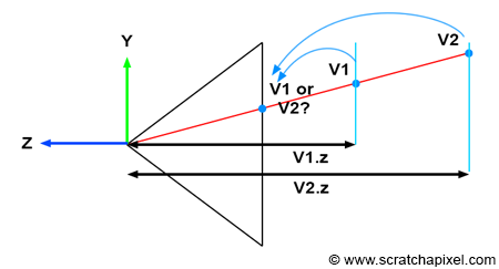
Understanding the importance of tracking the vertex z-coordinate in camera space becomes clearer when examining Figure 1. Imagine two vertices, v1 and v2, which, when projected onto the canvas, end up with identical raster coordinates (as depicted in Figure 1). If v1 is projected before v2, then v2 will appear visible in the image when, in fact, it should be v1 (since v1 is clearly in front of v2). However, by storing the z-coordinate of the vertices along with their 2D raster coordinates, we can determine which point is closest to the camera regardless of the order in which the vertices are projected, as demonstrated in the code snippet below.
// Project v2
Vec3f v2screen;
v2screen.x = near * v2camera.x / -v2camera.z;
v2screen.y = near * v2camera.y / -v2camera.z;
v2screen.z = -v2camera.z;

Vec3f v1screen;
v1screen.x = near * v1camera.x / -v1camera.z;
v1screen.y = near * v1camera.y / -v1camera.z;
v1screen.z = -v1camera.z;

// If the two vertices have identical coordinates in the image, then compare their z-coordinate
if (v1screen.x == v2screen.x && v1screen.y == v2screen.y && v1screen.z < v2screen.z) {
    // If v1.z is less than v2.z, then store v1 in the frame-buffer
    ....
}
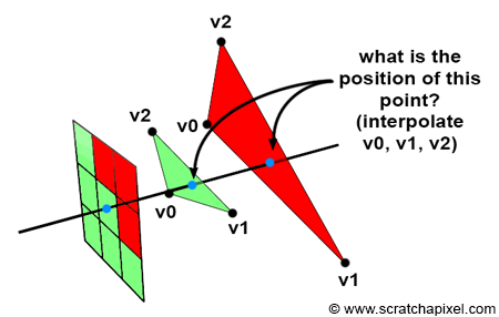
While our focus is on rendering triangles rather than individual vertices, the method we've just explored applies similarly to triangles. Specifically, we use the coordinates of the triangle vertices to locate the position of the point on the triangle that the pixel overlaps (including its z-coordinate). This concept is illustrated in Figure 2. If a pixel overlaps two or more triangles, we can calculate the position of the points on the triangles that the pixel overlaps, using the z-coordinates of these points, as we did with the vertices, to determine which triangle is closest to the camera. This method will be explained in detail in Chapter 4 (The Depth Buffer: Finding the Depth Value of a Sample by Interpolation)..
Screen Space is Also Three-Dimensional
To transition from camera space to screen space, a process during which the perspective divide occurs, we need to:
-
Perform the perspective divide, which involves dividing the x- and y-coordinates of a point in camera space by the point's z-coordinate.
$$ \begin{array}{l} P_{\text{screen}}.x = \dfrac{ \text{near} \times P_{\text{camera}}.x }{ -P_{\text{camera}}.z }\\ P_{\text{screen}}.y = \dfrac{ \text{near} \times P_{\text{camera}}.y }{ -P_{\text{camera}}.z }\\ \end{array} $$ -
Additionally, set the projected point's z-coordinate to the inverse of the original point's z-coordinate in camera space.
$$ P_{\text{screen}}.z = { -P_{\text{camera}}.z } $$
This essentially means that our projected point is not merely a 2D point but a 3D point. In other words, screen space is three-dimensional, not two-dimensional. Ed-Catmull, in his thesis, states:
"Screen space is also three-dimensional, but the objects have undergone a perspective distortion so that an orthogonal projection of the object onto the x-y plane would result in the expected perspective image" (Edwin Catmull's Thesis, 1974).
Similarly, in Paul S. Heckbert's thesis, "Fundamentals of Texture Mapping and Image Warping":
"3-D screen space is the 3-D coordinate system of the display, a perspective space with pixel coordinates (x, y) and depth z (used for z-buffering). It is related to world space by the camera parameters (position, orientation, and field of view). Finally, 2-D screen space is the 2-D subset of 3-D screen space without z."
Note that he distinguishes between 3D and 2D screen space here. However, he emphasizes that at some point in the process, the point being projected contains the 2D coordinates of the vertex onto the screen and a third z-coordinate, representing the point's original vertex depth value. This can be considered a 3D point within 3D space.
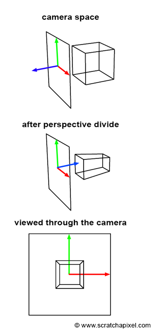
You should now be able to grasp the significance of these quotes, as well as the process illustrated in Figure 3. Initially, the geometry's vertices are defined in camera space (as shown in the top image). Then, each vertex undergoes a perspective divide, meaning the vertex's x- and y-coordinates are divided by their z-coordinate. As previously mentioned, we also set the resulting projected point's z-coordinate to the inverse of the original vertex's z-coordinate. This action implies a change in the direction of the z-axis within the screen space coordinate system, causing the z-axis to point inward rather than outward, as seen in the middle image of Figure 3. Importantly, the object that results from this process is not only a deformed version of the original object but also a three-dimensional one.
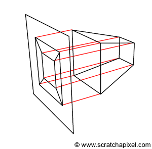
Furthermore, what Edwin Catmull means by "an orthogonal projection of the object onto the x-y plane, would result in the expected perspective image," is that once the object is in screen space, tracing lines perpendicular to the x-y image plane from the object to the canvas yields a perspective representation of that object (as demonstrated in Figure 4). This observation is intriguing because it suggests that the image creation process can be viewed as a perspective projection followed by an orthographic projection. If the distinction between perspective and orthographic projection isn't entirely clear to you at this point, don't worry. It is the focus of the next lesson. However, try to retain this observation, as it will prove useful later on.
Remapping Screen Space Coordinates to NDC Space
In the previous lessons, we explained that once in screen space, the x- and y-coordinates of the projected points need to be remapped to NDC (Normalized Device Coordinates) space. We also mentioned that in NDC space, points on the canvas have their x- and y-coordinates within the range [0,1]. However, in the context of GPU processing, coordinates in NDC space fall within the range [-1,1]. This discrepancy is one of those conventions we need to navigate. Although we could adhere to the [0,1] convention, aligning with GPU standards for rasterization is preferable.
You might wonder why we didn't adopt the [-1,1] convention from the start. There are several reasons. One is that, in our view, the term "normalize" should imply that the value being normalized falls within the range [0,1]. Additionally, it's beneficial to recognize that various rendering systems adopt different conventions regarding NDC space. For example, the RenderMan specifications define NDC space as spanning the range [0,1].
Therefore, once points have been transformed from camera space to screen space, the subsequent step is to remap them from the [l,r] range for the x-coordinate and the [b,t] range for the y-coordinate, to the [-1,1] range. The terms \(l\), \(r\), \(b\), and \(t\) correspond to the left, right, bottom, and top coordinates of the canvas, respectively.
What the \(l\), \(r\), \(b\), and \(t\) coordinates are and how to calculate them is explained in the lesson The Pinhole Camera Model: Implementing a Virtual Pinhole Camera). As a quick reminder, the depends on the focal length (in mm or inches), the film aperture width and height (in mm or inches) and the z-near clipping planes.
By rearranging the terms, we can derive an equation that accomplishes the desired remapping. Given the condition \(l < x < r\), where x represents the x-coordinate of a 3D point in screen space (bearing in mind that points in screen space are now considered three-dimensional), subtracting l from the equation yields:
$$0 < x - l < r - l$$Dividing all terms by \(r-l\) results in:
$$ 0 < \dfrac{x - l}{r - l} < 1 $$Expanding the middle term of the equation gives us:
$$0 < \dfrac{x}{r - l} - \dfrac{l}{r - l} < 1$$Multiplying all terms by 2 yields:
$$0 < 2 \cdot \dfrac{x}{r - l} - 2 \cdot \dfrac{l}{r - l} < 2$$Subtracting 1 from all terms results in:
$$-1 < 2 \cdot \dfrac{x}{r - l} - 2 \cdot \dfrac{l}{r-l} - 1 < 1$$Developing and regrouping the terms, we arrive at:
$$ \begin{array}{l} -1 < 2 \cdot \dfrac{x}{r - l} + \dfrac{-2l + l - r}{r-l} < 1 \\ -1 < 2 \cdot \dfrac{x}{r - l} + \dfrac{-l - r}{r-l} < 1 \\ -1 < \color{red}{\dfrac{2x}{r - l}} \color{green}{- \dfrac{r + l}{r-l}} < 1 \end{array} $$This equation is crucial because the red and green terms in the middle become the coefficients of the perspective projection matrix, which we will explore in the next lesson. For now, this formula is used to remap the x-coordinate of a point in screen space to NDC space, ensuring any point on the canvas falls within the [-1,1] range in NDC space. Applying the same logic to the y-coordinate, we get:
$$-1 < \color{red}{\dfrac{2y}{t - b}} \color{green}{- \dfrac{t + b}{t-b}} < 1$$Putting Things Together
At the end of this lesson, we are equipped to perform the first stage of the rasterization algorithm, which can be broken down into two steps:
-
Converting a point from camera space to screen space. This step essentially projects a point onto the canvas. It's crucial to remember that we also need to retain the original point's z-coordinate. The point in screen space is three-dimensional, and its z-coordinate will be instrumental in addressing the visibility problem later on.
$$ \begin{array}{l} P_{\text{screen}}.x = \dfrac{ \text{near} \times P_{\text{camera}}.x }{ -P_{\text{camera}}.z }\\ P_{\text{screen}}.y = \dfrac{ \text{near} \times P_{\text{camera}}.y }{ -P_{\text{camera}}.z }\\ P_{\text{screen}}.z = { -P_{\text{camera}}.z }\\ \end{array} $$ -
Converting the x- and y-coordinates of these points in screen space to NDC space using the formulas below:
$$ \begin{array}{l} -1 < \dfrac {2x}{(r -l)} - \dfrac {r + l}{(r-l)} < 1\\ -1 < \dfrac {2y}{(t - b)} - \dfrac {t + b}{(t-b)} < 1 \end{array} $$Here, \(l\), \(r\), \(b\), and \(t\) represent the left, right, bottom, and top coordinates of the canvas, respectively.
To transition from NDC space to raster space, we simply remap the x- and y-coordinates in NDC space to the [0,1] range and then multiply the resulting numbers by the image width and height, respectively (note that in raster space, the y-axis direction is inverted compared to NDC space). This conversion process is reflected in the following code snippet:
float nearClippingPlane = 0.1;
// Point in camera space
Vec3f pCamera;
worldToCamera.multVecMatrix(pWorld, pCamera);
// Convert to screen space
Vec2f pScreen;
pScreen.x = nearClippingPlane * pCamera.x / -pCamera.z;
pScreen.y = nearClippingPlane * pCamera.y / -pCamera.z;
// Now convert point from screen space to NDC space (range [-1,1])
Vec2f pNDC;
pNDC.x = 2 * pScreen.x / (r - l) - (r + l) / (r - l);
pNDC.y = 2 * pScreen.y / (t - b) - (t + b) / (t - b);
// Convert to raster space and set point's z-coordinate to -pCamera.z
Vec3f pRaster;
pRaster.x = (pNDC.x + 1) / 2 * imageWidth;
// In raster space, y-direction is inverted
pRaster.y = (1 - pNDC.y) / 2 * imageHeight;
// Store the point's camera space z-coordinate (as a positive value)
pRaster.z = -pCamera.z;
It's important to note that the coordinates of points or vertices in raster space are still defined as floating-point numbers here, not integers (which is typically the case for pixel coordinates).
What's Next?
Having projected the triangle onto the canvas and converted these projected vertices to raster space, both the triangle's vertices and the pixels now exist within the same coordinate system. We are now ready to iterate over all the pixels in the image and use a technique to determine if they are contained within the flat triangle projected onto the screen. This will be the focus of the next chapter.