Light Transport
Reading time: 20 mins.It's neither simple nor complicated, but it is often misunderstood.
Light Transport
In a typical scene, light is likely to bounce off the surfaces of many objects before reaching the eye. As explained in the previous chapter, the direction in which light is reflected depends on the type of material (whether it is diffuse, specular, etc.). Thus, light paths are defined by all the successive materials with which the light rays interact on their way to the eye.
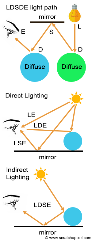
Imagine a light ray emitted from a light source, reflected off a diffuse surface, then a mirror surface, then a diffuse surface again before finally reaching the eye. If we label the light as L, the diffuse surface as D, the specular surface as S (a mirror reflection can be considered an ideal specular reflection, one in which the roughness of the surface is 0), and the eye as E, the light path in this particular example is LDSDE. Of course, all sorts of combinations are possible; this path can even be an "infinitely" long string of Ds and Ss. The one thing that all these rays have in common is an L at the start and an E at the end. The shortest possible light path is LE (when you look directly at something that emits light). If light rays bounce off the surface only once, which can be expressed using the light path notation as either LSE or LDE, then we have a case of direct lighting (direct specular or direct diffuse). Direct specular lighting occurs, for example, when the sun is reflected off a water surface. If you look at the reflection of a mountain in the lake, you are more likely to have an LDSE path (assuming the mountain is a diffuse surface), etc. In this case, we speak of indirect lighting.
Researcher Paul Heckbert introduced the concept of labeling paths in this manner in a paper published in 1990, entitled "Adaptive Radiosity Textures for Bidirectional Ray Tracing." It is not uncommon to use regular expressions to describe light paths compactly. For example, any combination of reflections off the surfaces of diffuse or specular materials can be written as: L(D|S)*E. In Regex (the abbreviation for regular expression), (a|b)* denotes the set of all strings with no symbols other than "a" and "b", including the empty string: {"", "a", "b", "aa", "ab", "ba", "bb", "aaa", ...}.
At this point, you might be thinking, "This is all good, but how does it relate to rendering?" As has been mentioned several times already in this lesson and the previous one, in the real world, light travels from sources to the eye. However, only a fraction of the rays emitted by light sources reaches the eye. Therefore, rather than simulating light paths from the source to the eye, a more efficient approach is to start from the eye and trace back to the source.
This is the typical approach in ray tracing. We trace a ray from the eye (generally called the eye ray, primary ray, or camera ray) and check whether this ray intersects any geometry in the scene. If it does (let's denote P as the point where the ray intersects the surface), we then need to do two things: compute how much light arrives at P directly from the light sources, and how much light arrives at P indirectly as a result of light being reflected by other surfaces in the scene.
-
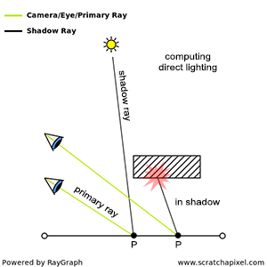
To compute the direct contribution of light to the illumination of P, we trace a ray from P to the source. If this ray intersects another object on its way to the light, then P is in the shadow of this light (which is why these rays are sometimes called shadow rays). This process is illustrated in Figure 2.
-
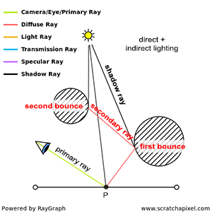
Indirect lighting comes from other objects in the scene reflecting light towards P, whether as a result of these objects reflecting light from a light source or as a result of these objects reflecting light that is itself bouncing off other objects in the scene. In ray tracing, indirect illumination is computed by spawning new rays, called secondary rays, from P into the scene (Figure 3). Let's explain in more detail how and why this works.
If these secondary rays intersect other objects or surfaces in the scene, it is reasonable to assume that light travels along these rays from the surfaces they intersect to P. We know that the amount of light reflected by a surface depends on the amount of light arriving at the surface as well as the viewing direction. Thus, to determine how much light is reflected towards P along any of these secondary rays, we need to:
-
Compute the amount of light arriving at the point of intersection between the secondary ray and the surface.
-
Measure how much of that light is reflected by the surface towards P, using the direction of the secondary ray as our viewing direction.
Remember that specular reflection is view-dependent: the amount of light reflected by a specular surface depends on the direction from which you are observing the reflection. Diffuse reflection, however, is view-independent: the amount of light reflected by a diffuse surface doesn't change with the direction. Thus, unless it's diffuse, a surface doesn't reflect light equally in all directions.
Computing how much light arrives at a point of intersection between a secondary ray and a surface is no different than computing how much light arrives at P. Computing how much light is reflected in the direction of the ray towards P depends on the surface properties and is generally done in what we call a shader. We will discuss shaders in the next chapter.
Other surfaces in the scene potentially reflect light to P. We don't know which ones, and light can come from all possible directions above the surface at P (light can also come from underneath the surface if the object is transparent or translucent, but we will ignore this case for now). However, because we can't test every single possible direction (it would take too long), we will only test a few directions instead. The principle is the same as when you want to measure, for instance, the average height of the adult population of a given country. There might be too many people in this population to compute that number exactly, however, you can take a sample of that population, let's say maybe a few hundred or thousand individuals, measure their height, make an average (sum up all the numbers and divide by the size of your sample), and get that way, an approximation of the actual average adult height of the entire population. It's only an approximation, but hopefully, it should be close enough to the real number (the bigger the sample, the closer the approximation to the exact solution). We do the same thing in rendering. We only sample a few directions and assume that their average result is a good approximation of the actual solution. If you've heard about the term Monte Carlo before, especially Monte Carlo ray tracing, that's what this technique is all about: shooting a few rays to approximate the exact amount of light arriving at a point. The downside is that the result is only an approximation. The bright side is that we get a result for a problem that is otherwise not tractable (i.e., it is impossible to compute exactly within any reasonable amount of finite time).
Computing indirect illumination is a recursive process. Secondary rays are generated from a point \(P\), which in turn generate new intersection points, from which other secondary rays are generated, and so on. We can count the number of times light is reflected from surfaces from the light source until it reaches \(P\). If light bounces off the surface of objects only once before it gets to \(P\), we have one bounce of indirect illumination. Two bounces mean light bounces off twice, three bounces three times, and so on.
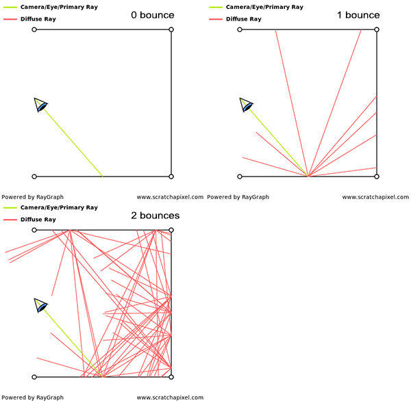
The number of times light bounces off the surface of objects can be infinite (imagine, for example, a situation in which a camera is inside a box illuminated by a light on the ceiling; rays would keep bouncing off the walls forever). To avoid this situation, we generally stop spawning secondary rays after a certain number of bounces (typically 1, 2, or 3). Note, though, that as a result of setting a limit to the number of bounces, \(P\) is likely to look darker than it actually should (since any fraction of the total amount of light emitted by a light source that took more bounces than the limit to arrive at \(P\), will be ignored). If we set the limit to two bounces, for instance, then we ignore the contribution of all other bounces above (third, fourth, etc.). However, fortunately, each time light bounces off the surface of an object, it loses a bit of its energy. This means that as the number of bounces increases, the contribution of these bounces to the indirect illumination of a point decreases. Thus, there is a point after which computing one more bounce makes such a little difference to the image that it doesn't justify the amount of time it takes to simulate it.
If we decide, for example, to spawn 32 rays each time we intersect a surface to compute the amount of indirect lighting (and assuming each one of these rays intersects a surface in the scene), then on our first bounce we have 32 secondary rays. Each one of these secondary rays generates another 32 secondary rays, which makes already a total of 1024 rays. After three bounces, we have generated a total of 32768 rays! If ray tracing is used to compute indirect lighting, it generally becomes quickly very expensive because the number of rays grows exponentially as the number of bounces increases. This is often referred to as the curse of ray tracing.

This long explanation shows you that the principle of computing the amount of light impinging upon \(P\), whether directly or indirectly, is simple, especially if we use the ray-tracing approach. The only sacrifice to physical accuracy we've made so far is to put a cap on the maximum number of bounces we compute, which is necessary to ensure that the simulation will not run forever. In computer graphics, this algorithm is known as unidirectional path tracing (it belongs to a larger category of light transport algorithms known as path tracing). This is the simplest and most basic of all light transport models based on ray tracing (it also goes by the name of classic ray tracing or Whitted-style ray tracing). It's called unidirectional because it only goes in one direction, from the eye to the light source. The part "path tracing" is pretty straightforward: it's all about tracing light paths through the scene.
Classic ray tracing generates a picture by tracing rays from the eye into the scene, recursively exploring specularly reflected and transmitted directions, and tracing rays toward point light sources to simulate shadows. (Paul S. Heckbert - 1990 in "Adaptive Radiosity Textures for Bidirectional Ray Tracing")
This method was originally proposed by Appel in 1968 ("Some Techniques for Shading Machine Rendering of Solids") and later developed by Whitted ("An Improved Illumination Model for Shaded Display" - 1979).
When the algorithm was first developed, Appel and Whitted considered only the cases of mirror surfaces and transparent objects. This limitation was because computing secondary rays (indirect lighting) for these materials required fewer rays than for diffuse surfaces. To compute the indirect reflection of a mirror surface, it is necessary to cast only a single reflection ray into the scene. If the object is transparent, one must cast one ray for the reflection and one ray for the refraction. However, when the surface is diffuse, approximating the amount of indirect lighting at a point \(P\) necessitates casting many more rays (typically 16, 32, 64, 128, up to 1024—though this number is not necessarily a power of 2, it usually is for reasons that will be explained in due time) distributed over the hemisphere oriented about the normal at the point of incidence. This process is far more costly than merely computing reflection and refraction (either one or two rays per shaded point), so initially, they developed their concept using specular and transparent surfaces as a starting point, as computers back then were significantly slower compared to today's standards. However, extending their algorithm to include indirect diffuse reflection was, of course, straightforward.
Other techniques besides ray tracing can be used to compute global illumination. It is worth noting, though, that ray tracing seems to be the most adequate method for simulating the way light propagates in the real world. Yet, the situation is not so straightforward. For example, with unidirectional path tracing, some light paths are more challenging to compute efficiently than others, especially those involving specular surfaces illuminating diffuse surfaces (or any surfaces, for that matter) indirectly. Let's consider an example.
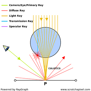
As depicted above, in this specific scenario, light emitted by the source at the top of the image is refracted through a transparent glass ball. This refraction effect concentrates all light rays towards a single point on the plane underneath, creating what is known as a caustic. Note that no direct light reaches point \(P\) directly from the light source (P is in the 'shadow' of the sphere); it arrives indirectly through the sphere by means of refraction and transmission. While it might seem more intuitive in this situation to trace light from the light source to the eye, given our decision to trace light rays in the opposite direction, let's examine the outcome.
When it comes to computing the amount of light arriving at \(P\) indirectly, assuming the surface at \(P\) is diffuse, we will spawn a series of rays in random directions to determine which surfaces in the scene redirect light towards \(P\). However, this approach fails to consider that all light comes from the bottom surface of the sphere. Theoretically, we could solve this problem by directing all rays from \(P\) toward the sphere, but since our method assumes no prior knowledge of how light travels from the light source to every point in the scene, this is not feasible (we have no prior knowledge of a light source above the sphere and no reason to assume that this light contributes to the illumination of \(P\) via transmission and refraction). All we can do is spawn rays in random directions as we do with all other surfaces, which is the essence of unidirectional path tracing. One of these rays might hit the sphere and be traced back to the light source, but we cannot guarantee that even a single ray will intersect with the sphere since their directions are chosen randomly. Therefore, in this particular case, we might fail to accurately compute the amount of light arriving at \(P\) indirectly.
Isn't one ray out of 10 or 20 enough? Yes and no. It's difficult to explain the technique used here to "approximate" the indirect lighting component of the illumination at point \(P\), but in short, it's based on probabilities and is somewhat similar to how one might measure an "approximation" of a variable using a poll. For instance, when attempting to determine the average height of the adult population of a specific country, it's impractical to measure every individual's height. Instead, a sample—a subset of that population—is taken, the average height of this sample is measured, and it's assumed that this figure is close enough to the actual average height of the entire population. Although the theory behind this technique is complex (requiring mathematical validation rather than being purely empirical), the concept itself is relatively straightforward. This same approach is applied here to approximate the indirect lighting component: random directions are chosen, the amount of light coming from these directions is measured, the results are averaged, and this number is taken as an "approximation" of the actual amount of indirect light received by \(P\). This technique is known as Monte Carlo integration, a critical method in rendering that is detailed extensively in several lessons from the "Mathematics and Physics of Computer Graphics" section. To understand why one ray out of 20 secondary rays is not ideal in this particular case, these lessons are essential reading.
Using Heckbert's light path naming convention, paths of the kind LS+DE are generally challenging to simulate in computer graphics using the basic approach of tracing the path of light rays from the eye to the source (or unidirectional path tracing). In Regex, the "+" sign accounts for any sequences that match the element preceding the sign one or more times. For example, "ab+c" matches "abc", "abbc", "abbbc", and so on, but not "ac". In this context, it means that situations in which light is reflected off the surface of one or more specular surfaces before it reaches a diffuse surface and then the eye (as in the example of the glass sphere) are difficult to simulate using unidirectional path tracing.
What do we do then? This is where the art of light transport comes into play.
While being simple and thus very appealing for this reason, a naive implementation of tracing light paths to the eye is not efficient in some cases. It works well when the scene consists only of diffuse surfaces but becomes problematic when the scene contains a mix of diffuse and specular surfaces (which is more often the case). So, what do we do? We search for a solution, as we usually do when faced with a problem. This search leads to the development of strategies (or algorithms) that can efficiently simulate all sorts of possible combinations of materials. We aim for a strategy in which LS+DE paths can be simulated as efficiently as LD+E paths. Since our default strategy falls short in this regard, new ones must be developed. This necessity led to the creation of new light transport algorithms that surpass unidirectional path tracing in solving this light transport problem. More formally, light transport algorithms are strategies (implemented as algorithms) that propose solutions to efficiently solving any combination of possible light paths, or more generally, light transport.
There are not many light transport algorithms, but still, quite a few exist. It's important to note that nothing dictates that ray tracing must be used to solve the problem. The choice of method is open. Many solutions employ what is known as a hybrid or multi-pass approach. Photon mapping is an example of such an algorithm. It requires the pre-computation of some lighting information, stored in specific data structures (such as a photon map or a point cloud), before rendering the final image. Difficult light paths are resolved more efficiently by leveraging the information stored in these structures. Recall the example of the glass sphere, where we mentioned having no prior knowledge of the light's existence above the sphere? Photon maps serve to pre-examine the scene and gain some prior knowledge about where light "photons" will go before rendering the final image, based on that concept.
While multi-pass algorithms were quite popular some years ago due to their ability to render complex phenomena like caustics, which were challenging to achieve with pure ray tracing, they come with significant drawbacks. These include the complexity of managing multiple passes, the necessity for additional computational work, the requirement to store extra data on disk, and the delay in starting the actual rendering process until all pre-computation steps are completed. Despite these challenges, for a time, such algorithms were favored because they enabled the rendering of effects otherwise deemed too costly or impossible with straightforward ray tracing, thus offering a solution—albeit a cumbersome one—where none existed before. However, a unified approach, one that does not require multi-pass processes and integrates seamlessly with existing frameworks, is preferable. For instance, within a ray tracing framework, an ideal solution would be an algorithm that relies solely on ray tracing, eliminating the need for any pre-computation.
Several algorithms have been developed that are based exclusively on ray tracing. Extending the concept of unidirectional path tracing, we find the bi-directional path tracing algorithm. It employs a relatively straightforward idea: for every ray cast from the eye into the scene, a corresponding ray is cast from a light source into the scene, with efforts made to connect their paths using various strategies. An entire section of Scratchapixel is dedicated to light transport, where some of the most significant light transport algorithms, including unidirectional path tracing, bi-directional path tracing, Metropolis light transport, instant radiosity, photon mapping, radiosity caching, and more, are reviewed.
Summary
A common myth in computer graphics is that ray tracing is the ultimate and sole method for solving global illumination. While ray tracing provides a natural and intuitive way to consider light travel in the real world, it also has its limitations. Light transport algorithms can be broadly categorized into two groups:
-
Those not utilizing ray tracing, such as photon or shadow mapping, radiosity, etc.
-
Those exclusively using ray tracing.
As long as an algorithm efficiently captures light paths challenging for the traditional unidirectional path tracing algorithm, it qualifies as a contender to solve the LS+DE problem.
Modern implementations tend to favor ray tracing-based light transport methods, primarily because ray tracing offers a more coherent approach to modeling light propagation in a scene and facilitates a unified method for computing global illumination without the need for auxiliary structures or systems to store light information. However, it's important to note that while such algorithms are becoming standard in offline rendering, real-time rendering systems still rely heavily on alternative approaches, not designed for ray tracing, and continue to use techniques like shadow maps or light fields to compute direct and indirect illumination.