Coordinate Systems
Reading time: 25 mins.Exploring Coordinate Systems
Coordinate systems are a fundamental aspect of the graphics pipeline, serving as a straightforward yet crucial concept. Often introduced in early education within the context of geometry, understanding coordinates is a stepping stone towards grasping matrices more thoroughly.
In our preceding discussion, we highlighted that in computer graphics (CG), points and vectors are defined by three real numbers. These numbers signify a signed distance from a line's origin to a point's location on that line. Imagine drawing a line and marking its center as the origin. This mark serves as our reference point, the baseline from which we measure distances to other points. A point situated to the right of the origin is assigned a positive signed distance, indicating it is greater than zero. Conversely, a point on the left has a negative value.
We consider the line to extend indefinitely in both directions from the origin. This implies that the distance between any two points on the line could be boundlessly large. Nevertheless, in computing, the representation of numbers is limited by the number of bits used for encoding, setting a practical cap on the values we can handle. Fortunately, this limit is typically sufficient for constructing the 3D scenes intended for rendering in CG, so the computational constraints are not a significant concern for now.
With our line and origin established, we introduce regular markings (unit lengths) on either side of the origin, transforming our line into a measurable scale. This scale allows us to determine the coordinate of a point relative to the origin, with "coordinate" referring to the signed distance from the origin to the point. In the realms of computer graphics and mathematics, this scale is known as an axis.
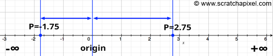
Consider a scenario where a point does not lie directly on the axis. We can still ascertain its coordinate by projecting it onto the axis with a vertical line (assuming the axis is horizontal), typically using a line perpendicular to the axis. The point where this vertical line intersects the axis gives us the coordinate of the point in relation to that axis, teaching us how to locate a point's coordinate along an axis.
Exploring Dimensions and Cartesian Coordinate Systems
Expanding on the concept of coordinate systems, let's delve into how dimensions are incorporated, starting with what we've previously called the x-axis—our horizontal ruler. By introducing another ruler at a right angle to the x-axis at its point of origin, we create the y-axis. This setup allows us to determine both the x- and y-coordinates of any point by drawing perpendicular lines to each axis and measuring their distances from the origin, paralleling the method described earlier. Consequently, we can assign an arbitrary point two coordinates: one for its position along the x-axis and another for its placement on the y-axis. Through this mechanism, a two-dimensional space, or plane, is defined by the intersection of these two axes.
Imagine plotting several points on a sheet of paper; this action takes place within a two-dimensional space. When we draw two axes on this paper—one for each dimension—and measure each point's position using these axes, we effectively establish a coordinate system. If these rulers intersect at right angles, they form what is known as a Cartesian coordinate system.
To denote a point's coordinates within this system, we use an ordered pair, which consists of two numbers separated by a comma. In Cartesian coordinate systems, it is standard practice to list the x-coordinate (horizontal) first, followed by the y-coordinate (vertical). For instance, a point with an x-coordinate of 2.5 and a y-coordinate of 2.25 would be represented as (2.5, 2.25), as seen in Figure 2. This notation simplifies to understanding the point's location as 2.5 units to the right and 2.25 units above the origin. This method of describing a point's coordinates will be used in future discussions.

With this knowledge, we've established how to create a two-dimensional Cartesian coordinate system and how to define the coordinates of a 2D point within it. It's crucial to recognize that within a given coordinate system, the coordinates of points are unique, meaning the same point cannot have different coordinates simultaneously.
Although any number of coordinate systems can be defined within a plane, for simplicity, let's consider only two Cartesian coordinate systems drawn on a single sheet of paper. The coordinates assigned to a point on this paper will vary depending on the coordinate system used. For example, in Figure 3, point P is assigned coordinates (-1, 3) in coordinate system A and (2, 4) in coordinate system B, illustrating that the physical location of the point remains unchanged despite the differing coordinates.
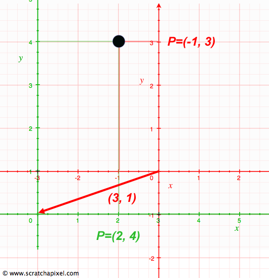
To translate a point's coordinates from one system to another—say, from A to B—an essential operation in computer graphics (CG) and mathematics, we simply add the values (3, 1) to its coordinates in system A to obtain its coordinates in system B. Similarly, subtracting these values from the coordinates in system B returns them to their values in system A. This process highlights the concept of additive inverses and their role in navigating between coordinate systems.
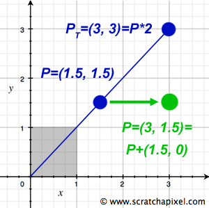
Moreover, operations like translation—moving a point to a new location within the same coordinate system—and scale—altering a point's coordinates through multiplication—demonstrate the application of linear operators to point coordinates. Scaling, for instance, shifts a point along the line extending through both the point and the origin, emphasizing the transformational relationship between points and vectors. Further exploration of these concepts will continue in subsequent lessons.
Extending to the Third Dimension
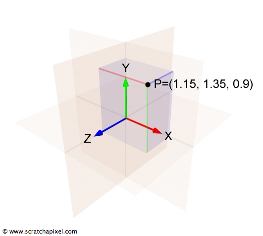
The transition from 2D to 3D coordinate systems is a natural progression that introduces a third axis—known as the z-axis—which is orthogonal (perpendicular) to both the x-axis and the y-axis, thereby adding depth to the previously flat representation. In this setup, the x-axis extends to the right, the y-axis stretches upwards, and the z-axis projects backward, appearing to come out of the screen when viewed with the x-axis pointing rightward. This arrangement, while not the only possible one, will be consistently applied throughout our discussions on Scratchapixel. This three-dimensional framework defines what is more formally recognized as Euclidean space, a cornerstone concept in geometry.
To delve deeper, especially for those interested in the formal aspects of coordinate systems, we turn to the principles of linear algebra. Here, the concept of a basis becomes essential. In the context of a coordinate system—whether it's one-dimensional with a single axis, two-dimensional with two axes, or three-dimensional as now introduced—the axes constitute the system's basis. A basis is a collection of linearly independent vectors that, through linear combinations, can represent any vector (or point) within a specific vector space (the coordinate system itself). Vectors within a set are considered linearly independent if none of them can be expressed as a linear combination of the others within the same set. The operation known as change of basis, or altering the coordinate system, plays a significant role in both mathematics and the graphics pipeline, facilitating the transition between different perspectives and dimensions within a given space.
Understanding Left-Handed vs. Right-Handed Coordinate Systems
The concept of coordinate system handedness introduces a layer of complexity due to varying conventions. This complexity is best illustrated by considering the orientation of the z-axis in relation to the x-axis (right vector) and y-axis (up vector). When visualizing your screen as the XY plane, with the y-axis pointing upwards and the x-axis extending to the right, the z-axis (also known as the forward or down vector) can either point towards the screen or towards you, indicating depth's direction.
To distinguish between these orientations, we refer to the first arrangement as the left-hand coordinate system and the second as the right-hand coordinate system. The distinction between these two types of systems was made clearer by physicist John Ambrose Fleming, who introduced the left-hand and right-hand rules.
The differentiation between left-handed and right-handed systems is straightforward: with the x-axis directed to the right and the y-axis upwards, a z-axis that points away from you defines a left-hand coordinate system. Conversely, if the z-axis points towards you, you're dealing with a right-hand coordinate system.
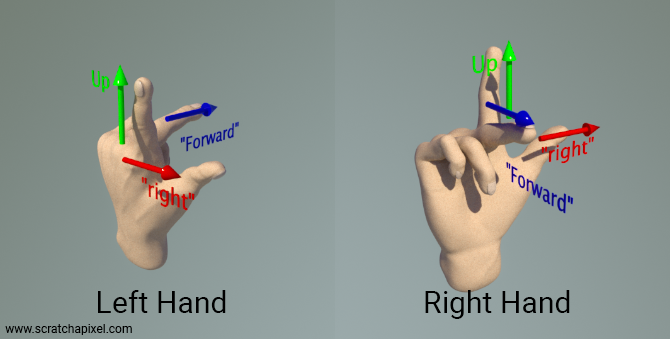
To easily recall the orientation of each coordinate system, you can use your hands as a mnemonic device. Assign your thumb, index finger, and middle finger to represent the x, y, and z-axes, respectively. This order naturally matches the way we extend our fingers. Perform this with both your left and right hand, orienting your thumb to the right and your index finger upward. Your middle finger will then point in the direction of the z-axis:
-
With your left hand, the z-axis points away from you.
-
With your right hand, the z-axis points towards you.
This method might require some dexterity but effectively aids in consistently remembering the orientation of the z-axis in these coordinate systems. Thus, the terms "left-hand" and "right-hand" coordinate systems, or the "handedness" of a system, are derived from this physical representation.
The topic of handedness is one of the most debated issues in computer graphics (at least from what I have observed) because it's a constant source of confusion, especially for people learning computer graphics. This is also because I have never seen, or am not aware of, a resource that is authoritative on the subject and where the topic is explained clearly, without ambiguity, and with illustrations.
The confusion arises from several sources:
-
On one hand, I have personally used several ways of explaining this concept throughout my career by proposing different configurations. I will come back to this.
-
The confusion also stems from the fact that the Y and Z axes can be inverted depending on whether you are a mathematician or a physicist. No, that's incorrect, but I left that sentence on purpose to ensure you’re paying attention. The X and Y axes are not inverted. The convention revolves around deciding whether the up vector, the one that points toward your ceiling or the sky, is either the Z or the Y vector. This is not an inversion of labels but a choice of how you orient the coordinate system. However, the point is, once you have oriented that coordinate system using your preferred convention—either using the Z or Y axis as the up vector—you can then define whether it's a left- or right-handed coordinate system.
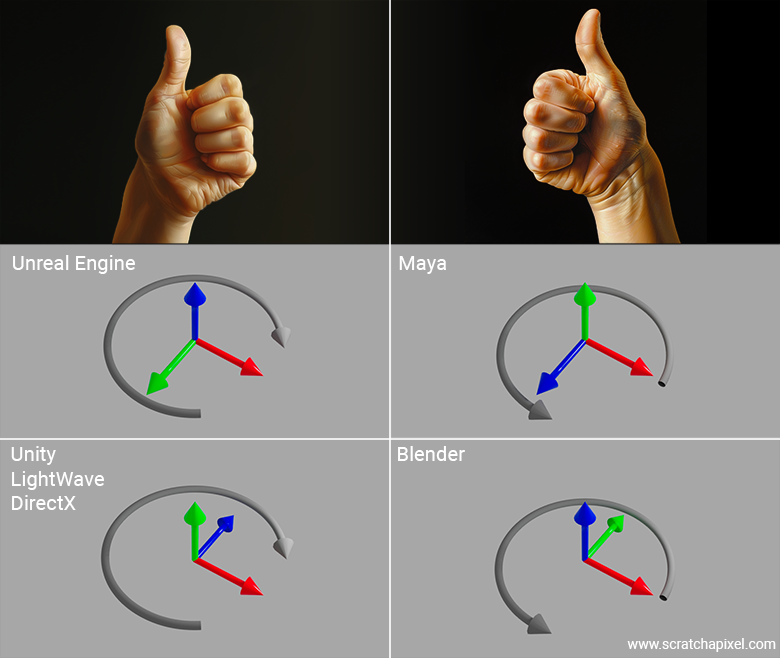
The best way to explain this is through an example. Let’s take the coordinate system used by Unreal Engine as an example. If you think that when the X-axis points to the right, the Unreal Engine coordinate system is a right-hand coordinate system—because aligning your right-hand thumb, index finger pointing up, and middle finger pointing toward you should match—you are wrong. Don’t worry, everybody gets lost with this at least once in their life.
In fact, if you look at the coordinate system as displayed in Unreal Engine’s interface, you’ll notice that the axis pointing upwards is blue: that’s the Z-axis. The axis pointing toward you is green: that’s the Y-axis. And if you read Unreal Engine’s documentation, it tells you that this coordinate system is a left-handed coordinate system. What? Why?
Because, in reality, all you need to do when using your fingers—whether they belong to your left or right hand—is to associate the X-axis with your thumb, the Y-axis with your index finger, and the Z-axis with your middle finger. That's it. Thumb: red, X. Index finger: green, Y. Middle finger: blue, Z. Now, the thing is, if you try this with your right hand in the Unreal Engine coordinate system, you’ll see that no matter how you twist your wrist, arm, or fingers, you won’t be able to match the diagram. In fact, if you point your right thumb to the right and your index finger toward you, your middle finger (representing the Z-axis) will point downward. So, it really is a left-hand coordinate system.
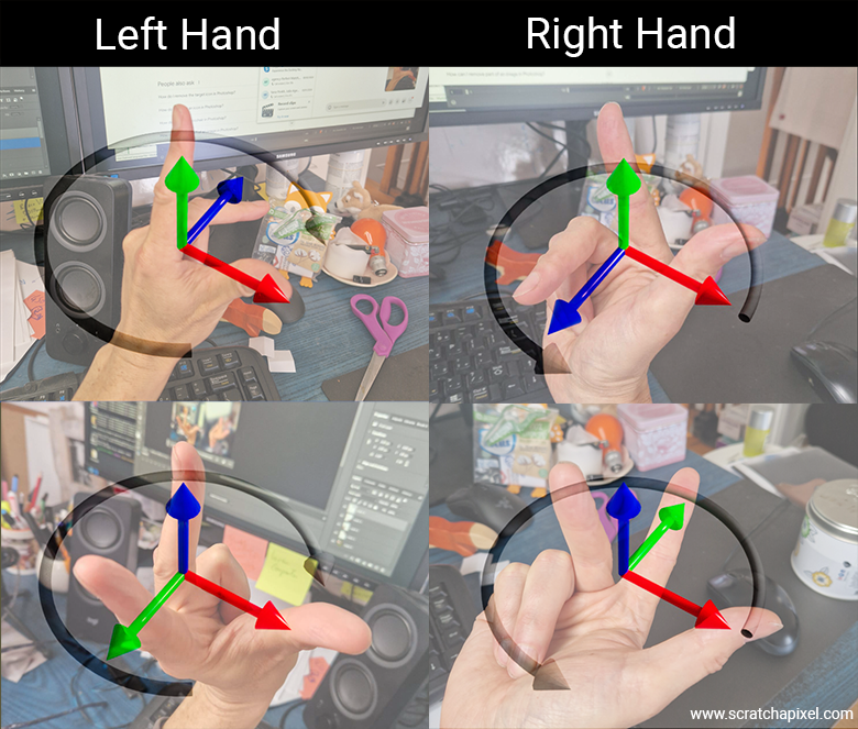
Doing the exercise with your left hand requires a 90-degree bend between your hand and forearm, which is quite difficult. But if you manage to do it, your fingers will eventually align with the axes of Unreal Engine’s coordinate system as displayed in its interface.
The secret—quite simple once someone explains it to you—is to use only the method I’ve just given you. Spread out your fingers in order: thumb, index, middle, and say out loud for each finger: X, Y, Z. That's it. Then, orient your fingers to match the coordinate system of the software you’re using, and you’ll find out whether the software uses a left- or right-hand coordinate system. And by the way, if the letters X, Y, Z are not displayed on the screen, rely on the colors. Normally, unless someone is crazy enough to make the problem even more confusing, everyone should be using red, green, and blue to designate the X, Y, and Z axes respectively.
Now that you're an expert and can impress your friends with this, let’s see if you’ve really understood the concept. Let’s look at other software like Maya and Blender and see which coordinate system they use.
Why is the choice of a left- or right-hand coordinate system important? Strictly speaking, it isn't crucial, but the choice of system does have consequences, such as how normals are oriented when they are calculated by iterating along the vertices that form a polygon. Consider the following example in which a triangle is defined by three vertices: \(v_0 = (0, 0, 0)\), \(v_1 = (0, 0, 1)\), and \(v_2 = (1, 0, 0)\). The following figure shows this triangle drawn for both left- and right-hand coordinate systems.
Now, lets calculate the normal for both triangles. Given vertices (same for both systems):
-
\(V_0 = (0, 0, 0)\)
-
\(V_1 = (0, 0, 1)\)
-
\(V_2 = (1, 0, 0)\)
We compute the triangle edges:
1. \(\mathbf{v1} = V_1 - V_0 = (0, 0, 1)\)
2. \(\mathbf{v2} = V_2 - V_0 = (1, 0, 0)\)
Now, the cross product:
$$\mathbf{N} = \mathbf{v1} \times \mathbf{v2} = (0, 0, 1) \times (1, 0, 0) = (0, 1, 0)$$I realized after writing this that we only touch on vector dot and cross products in the next chapters. If you're unfamiliar with these concepts, don't panic. Just keep reading the next few pages, and eventually, you can come back to this section once you're comfortable with what the cross product is.
We get \((0, 1, 0)\), regardless of the coordinate system. So, at first glance, the coordinate system's handedness does not affect the triangle's normal. Now look at Figure 9—you'll notice that the image of the two triangles is different. So, although the triangle data is the same, the visual outcome is different. That’s not what we want. Generally, when we generate the image of a 3D object, we want it to look the same regardless of the convention used internally. That's at least what one can expect.
In order to get the same triangle in the left-hand coordinate system as in the right-hand coordinate system, we would need to rotate the triangle around the Z-axis by 180 degrees. Note that whether you rotate the triangle drawn using a left-hand coordinate system to match the triangle drawn using a right-hand coordinate system, or the other way around, doesn't matter. In practice, we don’t perform a rotation. Instead, we negate the X-coordinates of the vertices (or the Z-coordinate, depending on your configuration) to switch from one system to the other. So, a visually similar triangle in the left-hand coordinate system (assuming we want to match the appearance of the triangle as drawn in the right-hand coordinate system) would have the following coordinates:
-
\(V_0 = (0, 0, 0)\)
-
\(V_1 = (0, 0, 1)\)
-
\(V_2 = (-1, 0, 0)\)
We compute the triangle edges:
1. \(\mathbf{v1} = V_1 - V_0 = (0, 0, 1)\)
2. \(\mathbf{v2} = V_2 - V_0 = (-1, 0, 0)\)
Now, the cross product:
$$\mathbf{N} = \mathbf{v1} \times \mathbf{v2} = (0, 0, 1) \times (-1, 0, 0) = (0, -1, 0)$$The normal is inverted. As a result, you can conclude that for the same visual result, the normal is reversed. So, if your initial data is defined with respect to a left-hand coordinate system, when drawn in a right-hand coordinate system (assuming the object looks visually the same), the normal of that object will be inverted (and vice versa). The choice of the coordinate system, therefore, has an immediate consequence: it determines the orientation of the normals of the triangles.
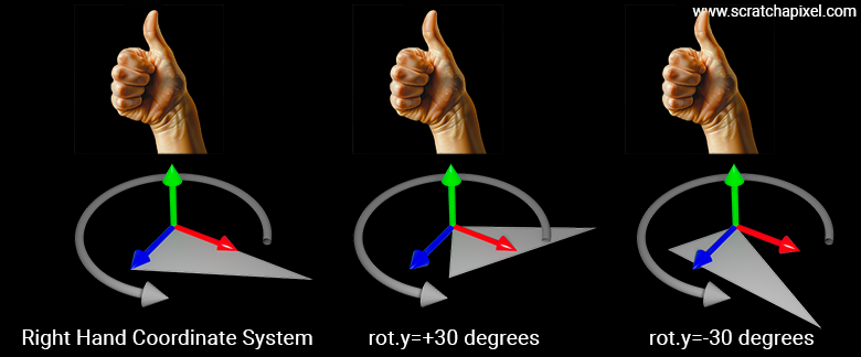
If you take your right hand and curl your fingers as shown in the picture below, the direction your fingers are pointing indicates the order of positive angle rotation in a right-hand coordinate system. For example, if you rotate the triangle by an angle of 30 degrees, the triangle will rotate as shown in the Figure 10. If the angle of rotation is -30 degrees, it will rotate in the opposite direction. With the right hand, you can see that your fingers indicate a counter-clockwise rotation (rotation opposite to the direction of a clock’s hands). This also implies that, assuming the vertices of the triangle are ordered in the same direction as your fingers, the normal will point in the direction of your thumb. For instance, assuming you compute (v2 - v1) and (v3 - v1), and that the vertices v1, v2, and v3 are defined in a counter-clockwise manner, the normal of the triangle will point along the direction indicated by your thumb.
The same principle applies to the left hand. If you curl your fingers, the direction they point indicates the direction the triangle will rotate, say around the up vector, when the rotation angle is positive (you can also do this for the x- and z-axes) in a left-hand coordnate system. The thumb will indicate the direction of the triangle’s normal when the vertices are ordered clockwise (according to the orientation given by your curled fingers).
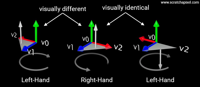
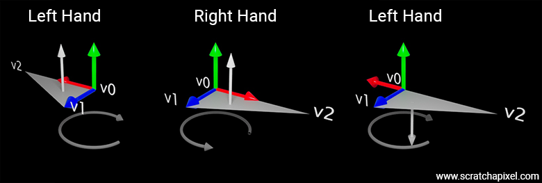
The following figure illustrates this concept with a triangle whose vertices are \(V_0 = (0,0,0)\), \(V_1 = (0,0,1)\), and \(V_2 = (2,0,0)\). In the left-hand coordinate system, if we follow the vertices from \(v1\) to \(v3\), we move in a clockwise manner. In the right-hand coordinate system, if we follow the vertices from \(v0\) to \(v1\) to \(v2\), we move counter-clockwise around the up vector. In both cases, the thumb indicates that the normal will point upward. This is mathematically sound since, as explained earlier, the vertex coordinates are the same, so \(e1 = v1 - v0\) and \(e2 = v2 - v0\) are the same, and thus the cross-product \(n = e1 \times e2\) is thus also the same.
However, as pointed out earlier, the triangles will look different. If we negate the x-coordinates of all vertices in the left-hand coordinate system to make the two triangles appear visually identical, note that following the vertices from \(v0\) to \(v3\) now results in a counter-clockwise rotation—opposite to the direction your fingers would curl. This means that the triangle’s normal will point in the opposite direction to the left-hand thumb; in other words, it will point downward when the triangle is in this configuration.
If you haven't grasped this yet, it's because when you rotate clockwise, the vertices will now appear in the following order: \(v0, v2, v1\). Therefore, \(e1 = v2 - v0\) and \(e2 = v1 - v0\), and the cross product of these two vectors will give you the normal (0, -1, 0).
This example demonstrates that the choice between a left-hand and right-hand coordinate system affects two main things:
-
Rotation direction: Knowing whether the object will rotate clockwise or counter-clockwise when the angle is positive or negative, which you can determine using the method of curling your left or right hand’s fingers.
-
Normal direction: Using the curling-finger method again, the thumb indicates the direction in which the normal will point, assuming the vertices are ordered according to the orientation of the fingers. In the left-hand coordinate system, the normal will point upward when the vertices are ordered clockwise. In the right-hand coordinate system, the normal will point upward when the vertices are ordered counter-clockwise.
Most of these details are configurable in modern graphics APIs, such as Metal, Vulkan, or DirectX. You can specify the order in which the engine expects the vertices to be provided. These parameters are defined when you create what is called in these APIs a graphics pipeline. Here’s an example of how these controls are set in the Vulkan API for example:
VkPipelineRasterizationStateCreateInfo info = {
	...
	.polygonMode = VK_POLYGON_MODE_FILL,
	.cullMode = VK_CULL_MODE_BACK_BIT,
	.frontFace = VK_FRONT_FACE_COUNTER_CLOCKWISE,
	...
};
This doesn’t affect how these APIs calculate normals because, in fact, graphics APIs do not calculate normals for you; it’s up to you to compute them in the vertex or fragment shaders. However, the orientation of the normal you calculate in these shaders will depend on both the order in which your triangle’s vertices are defined and the order you've instructed the engine to expect, as this influences how the data used to compute the normal in the shaders is passed to them.
This is important because graphics engines implement a process called culling. Culling is the process of removing triangles whose normals are not facing the camera. These are considered back-facing triangles, which you may not want to render. However, modern graphics APIs also allow you to cull front-facing triangles, both front and back, or even disable culling entirely. But that’s not the point. The point is that if you choose to cull front or back-facing triangles, whether the triangles are considered front or back-facing depends on both the vertex ordering and the parameters you set to control this.
For Scratchapixel and the code developed to illustrate the concepts in the lessons, we consistently use the right-hand coordinate system. In this system, the Y-axis points upwards, the Z-axis (represented by your middle finger) points toward you, and the X-axis points to the right.
To conclude this topic, it's important to note that the handedness of the coordinate system you choose or are forced to use in a digital content creation tool, such as Blender, Maya, or Unreal Engine, isn't usually a major concern—until you start using several of these tools simultaneously in your workflow. For instance, you might use Houdini for VFX, Maya for modeling and animation, Blender for rendering, or Unreal Engine for game development. The specific combination of tools can vary.
The real issue arises when you export and import assets (notably geometry) between these tools. If they use different conventions for coordinate system handedness, you’ll need to process the data along the way—usually when importing. For example, imagine you're working in Maya, where the Y-axis is the up vector. If you import this geometry directly into Blender, where the Y-axis represents depth rather than the up vector, your geometry might appear lying down instead of standing upright (like a statue). In such cases, you'll need to swap the Y and Z coordinates of your object's vertices to correct the orientation.
Handedness disparities between software are one of the main sources of problems in production pipelines and can be particularly frustrating. The choice of one system over another is often driven by historical reasons rather than common sense or a desire to simplify life for artists and users. If you have the option to choose a convention, I recommend sticking to a right-hand coordinate system with the Y-axis as the up vector. This choice will save everyone a lot of headaches down the line.
Navigating the World Coordinate System
In the journey through 3D applications, we've uncovered how the positions and directions of points and vectors are anchored to the origin of a Cartesian coordinate system, constructed from three mutually perpendicular unit vectors that form its basis. This exploration revealed the possibility to craft numerous coordinate systems, each granting points and vectors a unique set of coordinates within its confines. Yet, paramount to the structure of most 3D environments is the world coordinate system. This master coordinate system sets the stage, offering the foundational x-, y-, and z-axes from which all other coordinate systems derive their orientation. It emerges as the cornerstone in the constellation of coordinate systems employed throughout the rendering pipeline, which includes those dedicated to objects, local environments (particularly in shading contexts), cameras, and screens. The intricacies of these systems will be unraveled progressively.
Core Concepts to Remember
While the fundamentals of basic geometry might already be familiar to many readers, the crux of this discussion leans more towards fostering familiarity with the terminology pervasive across computer graphics (CG) literature. In this narrative, the spotlight shines on coordinates, axes, and the Cartesian coordinate system as key terms. Further enriching this vocabulary is the introduction of linear operators, such as scaling and translation, instrumental in manipulating points and vectors. The takeaways extend beyond mere geometric principles to include an understanding that points are invariably linked to a coordinate system, amidst a realm where endless coordinate systems can be created, each bestowing a point with distinct coordinates.
Crucial, too, is recognizing the handedness of the coordinate system in use—be it within your programming endeavors or the APIs employed for image rendering. This discernment aids in navigating the nuances between the handedness of a coordinate system and the conventions adopted for axis orientation, ensuring a seamless integration of concepts across the spectrum of computer graphics applications.