Rectangular Area Light
Reading time: 6 mins.Preamble
Because each shape that an area light can have has its own specific implementation considerations, we have decided to dedicate one page per area light shape. More specifically, we will consider triangular, planar, disk, and finally spherical area lights. This preamble is repeated on each page to ensure that if you landed on one of these pages from an external link, you are aware that it is advisable to start by reading the page on the triangular area light. There, we will discuss some concepts that will be reused across the other light types and provide a general explanation about the code we will be using to implement these lights.
Also note that we strongly recommend that you read the lessons on Distributed Ray-Tracing and Stochastic Sampling and Sampling Strategies, which are corollaries to this one.
The Quad Area Light
Thankfully, the chapter on rectangular or quad area lights will be much shorter. First, because there's a lot of common code with the triangular area light, which we have already covered in the previous chapter, and second, because starting the sampling process by sampling the unit square and converting this sample to a square, whether bigger or smaller, a rectangle, or a parallelogram (a skewed rectangle) turns out to be straightforward. There is no need to do any form of special mapping here.
Note that we can already create a quad area light with just the code we have right now, since a quad can be created from two triangles. This option means we don't need any special code to handle the quad light, which is good (less code is good).
std::shared_ptr<TriangleLight> light0 = std::make_shared<TriangleLight>(
    Vec3f(-1, -1, 0),
    Vec3f(1, -1, 0),
    Vec3f(-1, 1, 0),
    Vec3f(5.f));

std::shared_ptr<TriangleLight> light1 = std::make_shared<TriangleLight>(
    Vec3f(1, -1, 0),
    Vec3f(1, 1, 0),
    Vec3f(-1, 1, 0),
    Vec3f(5.f));

Matrix44<float> xfm_light(0, 0, -1, 0, 0, 1, 0, 0, 1, 0, 0, 0, -1, 0, -4, 1);
prims.push_back(std::make_unique<Primitive>(light0, xfm_light));
prims.push_back(std::make_unique<Primitive>(light1, xfm_light));
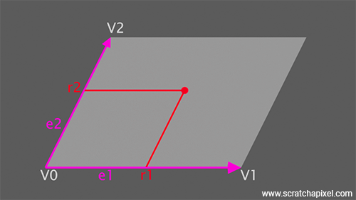
There is obviously a problem with this approach, which is that now you have two lights in your scene instead of one, whereas if you just used a quad light, you'd only have one. If you go with implementing a quad area light, you will need to derive the QuadLight class from the AreaLight base class, as with the triangular area light. For the QuadLight class, only three vertices are strictly necessary—three vertices from which we will be able to calculate the edges of the parallelogram, as shown in Figure 1.
QuadLight::QuadLight(const Vec3f& v0, const Vec3f& v1, const Vec3f& v2, const Vec3f& Le)
    : v0_(v0)
    , v1_(v1)
    , v2_(v2)
    , e1_(v1 - v0)
    , e2_(v2 - v0)
    , Ng_(e1_.Cross(e2_))
    , Le_(Le) {
    // Build a TriangleMesh made out of two triangles
    ...
}
Note that, as with triangular area lights, we won't be normalizing the normal calculated from the cross product of these two edges, as the length of the normal holds the area of the light. Again, as with the triangular light, we will use this property of the normal in the Sample method to calculate the sample's PDF (which, as a reminder, is 1 over the area) without having to explicitly calculate this area. Note also that in the QuadLight constructor, you will need to build a TriangleMesh rather than TriangleLight to represent the two triangles making up the quad. We leave this up to you to implement this method as there's no pedagogical value in doing so and it will bloat our sample code.
Sampling the area light is simple. We just use the edges of the parallelogram as the basis of a coordinate system to calculate the new position of the sample from the unit square onto the rectangular area light. The code is as follows:
Vec3f QuadLight::Sample(const DifferentialGeometry& dg, Sample3f& wi, float &tmax, const Vec2f& sample) const override {
    Vec3f d = (v0_ + e1_ * sample.x + e2_ * sample.y) - dg.P;
    tmax = d.Length();
    float d_dot_Ng = d.Dot(Ng_);
    if (d_dot_Ng >= 0) return 0;
    wi = Sample3f(d / tmax, (2.f * tmax * tmax * tmax) / std::abs(d_dot_Ng));
    return Le_;
}
Surprisingly simple. The rest is exactly like for the triangular light. The PDF variable effectively stores the value for the PDF, which is 1 over the area, a trick we explained in the previous chapter. So we won't be explaining it here again. We also have the \( r^2 \) factor to account for the inverse-square law and the cosine of the angle between the light sample direction and the light normal.
Let's conclude, as usual, with the output of the program (whose code you can find by following the GitHub link provided in the table of contents at the top of this page):
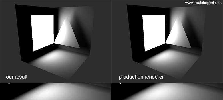
Note that the image produced by the production renderer seems to have less noise, particularly on the floor surface below the quad on the left and the triangle on the right. This is because renderers, such as Arnold in this case, use various techniques in addition to Monte Carlo integration, such as evaluating the contribution of the area light using a closed-form solution (not requiring a Monte Carlo method—thus noise-free) and cone sampling (check the next chapter to learn more about this technique).
The topic of using closed-form solutions for evaluating area lights will be the subject of a future lesson. This is, in itself, a pretty complex topic math-wise.
Another note regarding the values used for the radiant exitance of the two triangular area lights in option 1, which is 5. If you want to reproduce this example in a commercial renderer, you will need to set the light intensity to 20. This is because the radiant exitance represents the power per unit of surface area. Our triangle in this case has a surface area of 2 units (check the values of the vertices used for building the triangles). With two such lights, the final light power is indeed 20. The radiant exitance of 5 is multiplied by the surface area of the two triangles (2 units each), giving a total intensity value of 20 (5 multiplied by the surface area of 2x2).
As promised, much shorter. As you can see, the bulk of the work was done in the previous chapter. However, don't get too excited because implementing the next type of area light, which includes disk and spherical area lights, is going to be another kind of beast. In the next chapter, we will indeed learn about cone sampling vs. area sampling, which we have been using so far for triangular and rectangular area lights. See you in the next chapter.